1.35 BMP C220 - Stormwater System Inlet Protection
To prevent coarse sediment from entering stormwater systems prior to permanent stabilization of the disturbed area.
Use where inlets are to be made operational before permanent stabilization of the disturbed area.
Provide protection for all stormwater system inlets downslope and within 500 feet of a disturbed or construction area, unless those inlets are preceded by another sediment trapping device.
Table 3 - 11: Stormwater System Inlet Protection lists several options for inlet protection. All of the methods for stormwater system inlet protection are prone to plugging and require a high frequency of maintenance. Contributing areas should be limited to 1 acre or less. Emergency overflows may be required where stormwater ponding would cause a hazard. If an emergency overflow is provided, additional end-of-pipe treatment may be required. Table 3 - 11: Stormwater System Inlet Protection Applicable for heavy flows. Easy to maintain. Large area requirement: Applicable for heavy concentrated flows. Will pond. Can withstand traffic.
30’ x 30’ per acre.
1.35.3 Design and Installation Specifications
Excavated Drop Inlet Protection
An excavated impoundment around the inlet. Sediment settles out of the stormwater prior to entering the stormwater conveyance system..
Provide depth of 1 to 2 feet, as measured from the crest of the inlet structure.
Slope sides of excavation no steeper than 2H:1V.
Minimum volume of excavation 35 cubic yards.
Shape excavation to fit site with longest dimension oriented toward the longest inflow area.
Install provisions for collection and conveyance to prevent standing water problems.
Grade the approach to the inlet uniformly.
Drill weep holes into the side of the inlet.
Protect weep holes with screen wire and washed aggregate.
Seal weep holes when removing structure and stabilizing area.
It may be necessary to build a temporary dike to the down slope side of the structure to prevent bypass flow.
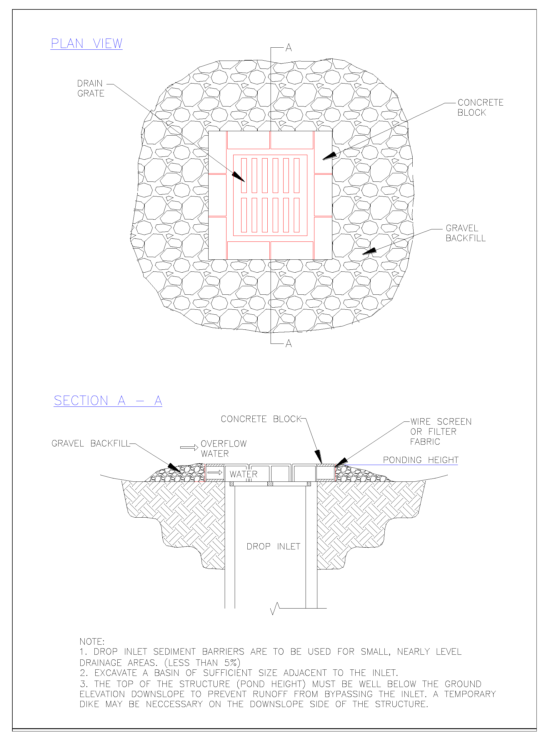
A block and gravel filter is a barrier formed around the stormwater system inlet with standard concrete blocks and gravel. See Figure 3 - 17: Drop Inlet with Block and Gravel Filter.
Provide a height 1 to 2 feet above inlet.
Recess the first row 2 inches into the ground for stability.
Support subsequent courses by placing a piece of 2x4 lumber through the block opening.
Lay some blocks in the bottom row on their side for dewatering the pool.
Place hardware cloth or comparable wire mesh with ½-inch openings over all block openings.
Place gravel just below the top of blocks on slopes of 2H:1V or flatter.
An alternative design is a gravel berm surrounding the inlet with the following characteristics:
Provide an inlet slope of 3H:1V.
Provide an outlet slope of 2H:1V.
Provide a 1-foot wide level stone area between the structure and the inlet.
Use inlet slope stones 3 inches in diameter or larger.
For outlet slope use gravel ½- to ¾-inch at a minimum thickness of 1-foot.
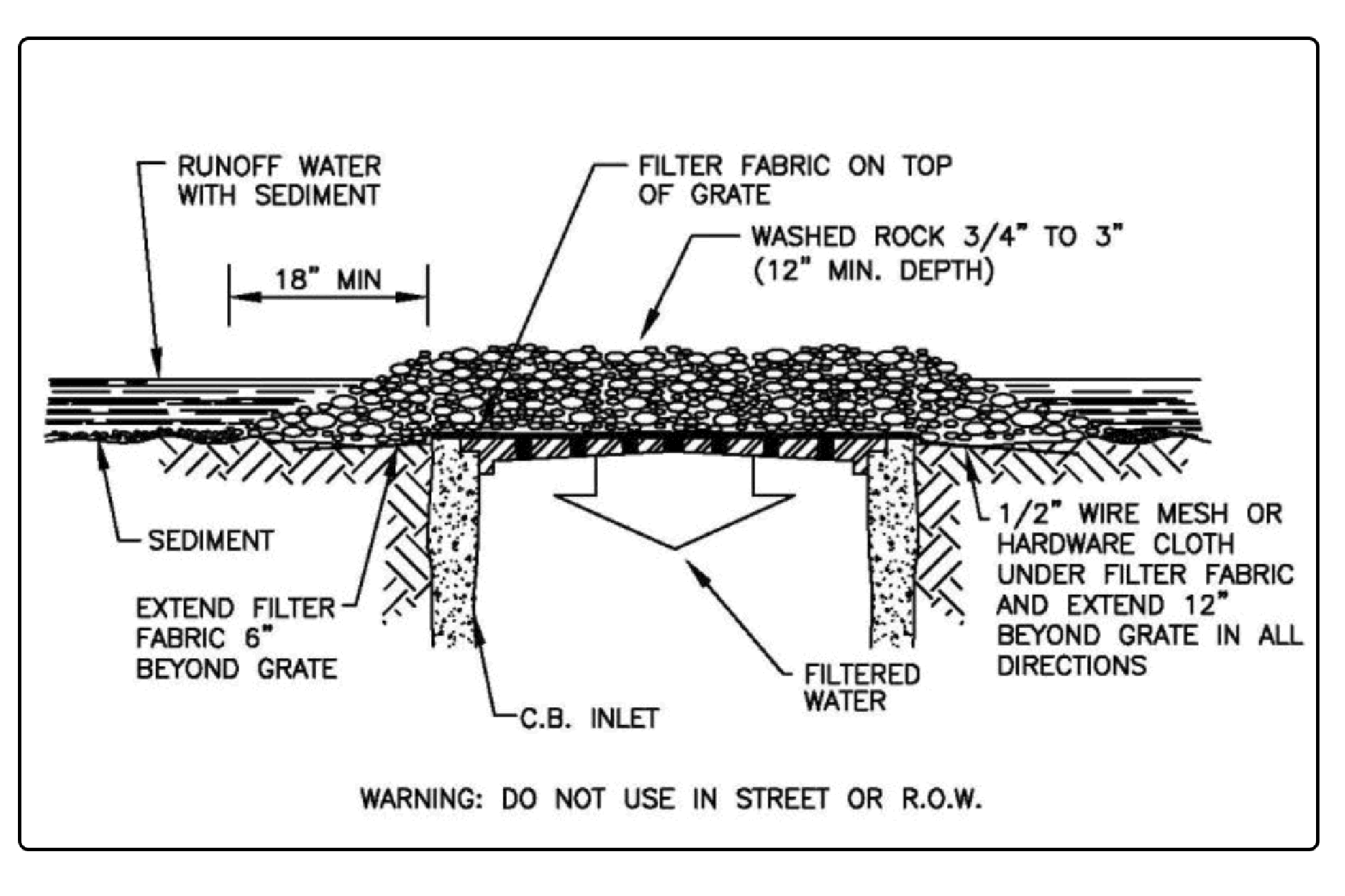
A gravel and wire mesh filter is a gravel barrier placed over the top of the inlet (see Figure 3 - 18: Gravel and Wire Mesh Filter). This structure does not provide an overflow.
Use a hardware cloth or comparable wire mesh with 1/2-inch openings.
Place wire mesh over the drop inlet so that the wire extends a minimum of 1-foot beyond each side of the inlet structure.
Overlap the strips if more than one strip of mesh is necessary.
Place coarse aggregate over the wire mesh.
Provide at least a 12-inch depth of aggregate over the entire inlet opening and extend at least 18-inches on all sides.
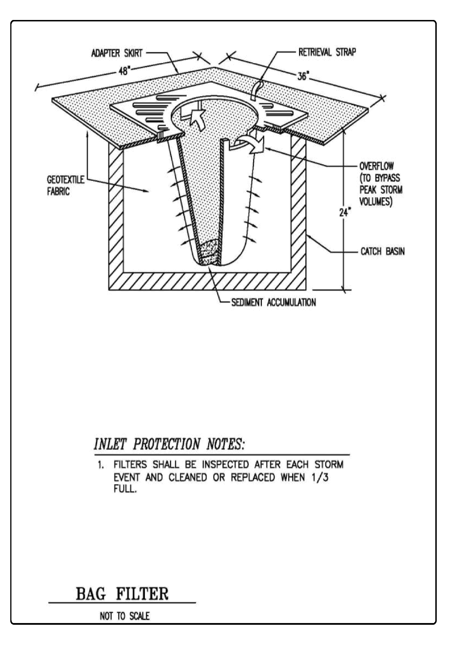
Inserts (Figure 3 - 19: Catch Basin Filter) shall be designed by the manufacturer for use at construction sites. The limited sediment storage capacity increases the frequency of inspection and maintenance required, which may be daily for heavy sediment loads. The maintenance requirements can be reduced by combining a catch basin filter with another type of inlet protection. This type of inlet protection provides flow bypass without overflow and therefore may be a better method for inlets located along active rights-of-way.
Provide a minimum of 5 cubic feet of storage.
Requires dewatering provisions.
Provide a high-flow bypass that will not clog under normal use at a construction site.
The catch basin filter is inserted in the catch basin just below the grating.
Figure 3 - 17: Drop Inlet with Block and Gravel Filter
Figure 3 - 18: Gravel and Wire Mesh Filter
Figure 3 - 19: Catch Basin Filter
Curb Inlet Protection with Wooden Weir
Barrier formed around a curb inlet with a wooden frame and gravel.
Use wire mesh with ½-inch openings.
Use extra strength filter cloth.
Attach the wire and filter fabric to the frame.
Pile coarse washed aggregate against the wire and fabric.
Place weight on frame anchors.
Block and Gravel Curb Inlet Protection
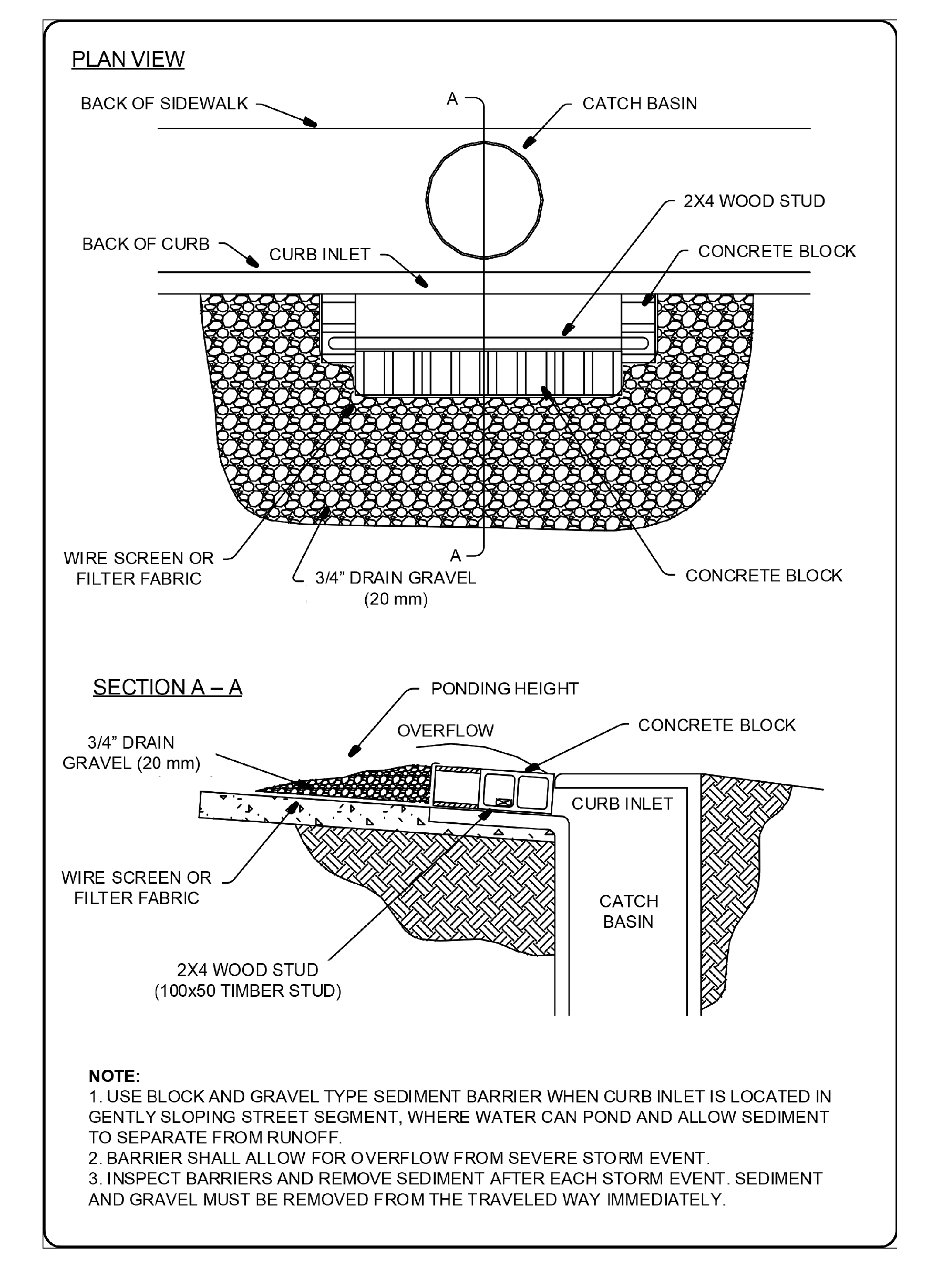
Barrier formed around an inlet with concrete blocks and gravel. See Figure 3 - 20: Block and Gravel Curb Inlet Protection.
Use wire mesh with ½-inch openings.
Place two concrete blocks on their sides abutting the curb at either side of the inlet opening. These are spacer blocks.
Place a 2x4 stud through the outer holes of each spacer block to align the front blocks.
Place blocks on their sides across the front of the inlet and abutting the spacer blocks.
Place wire mesh over the outside vertical face.
Pile coarse aggregate against the wire to the top of the barrier.
Figure 3 - 20: Block and Gravel Curb Inlet Protection
Curb and Gutter Sediment Barrier
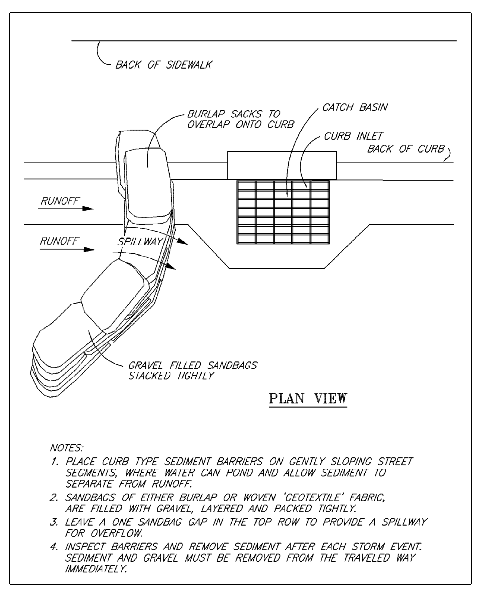
Sandbag or rock berm (riprap and aggregate) 3 feet high and 3 feet wide in a horseshoe shape. See Figure 3 - 21: Curb and Gutter Sediment Barrier.
Construct a horseshoe shaped berm, faced with coarse aggregate if using riprap, 3 feet high and 3 feet wide, at least 2 feet from the inlet.
Construct a horseshoe shaped sedimentation trap on the outside of the berm sized to sediment trap standards for protecting a culvert inlet.
Inspect inlet protection frequently, especially after storm events. If the insert becomes clogged, clean or replace it.
For systems using stone filters: If the stone filter becomes clogged with sediment, the stones must be pulled away from the inlet and cleaned or replaced. Since cleaning of gravel at a construction site may be difficult, an alternative approach would be to use the clogged stone as fill and put fresh stone around the inlet.
Do not wash sediment into the stormwater system while cleaning. Spread all excavated material evenly over the surrounding land area or stockpile and stabilize as appropriate.
Do not allow accumulated sediment to enter the stormwater system.
Inlet protection shall be removed when area is fully stabilized and erosion and sediment controls are no longer needed.
Figure 3 - 21: Curb and Gutter Sediment Barrier
