A sediment trap is a small temporary ponding area with a gravel outlet used to collect and store sediment from sites cleared and/or graded during construction. Install sediment traps, along with other perimeter controls, before any land disturbance takes place.
Sediment traps are intended for use on sites where the contributing area is less than 3 acres, with no unusual stormwater and surface water features, and a projected build-out time of six months or less. The sediment trap is a temporary measure (with a design life of approximately 6 months) and shall be maintained until the site area is permanently protected against erosion by the installation of vegetation and/or structures.
Sediment traps are only effective in removing sediment down to about the medium silt size fraction. Runoff with sediment of finer grades (fine silt and clay) will pass through untreated, emphasizing the need to control erosion to the maximum extent first.
When permanent facilities are used as temporary sedimentation facilities, the surface area requirement of a sediment trap must be met. If the surface area requirements are larger than the surface area of the permanent facility, then the trap or pond shall be enlarged to comply with the surface area requirement.
A skimmer may be used for the sediment trap outlet.
1.42.3 Design and Installation Specifications
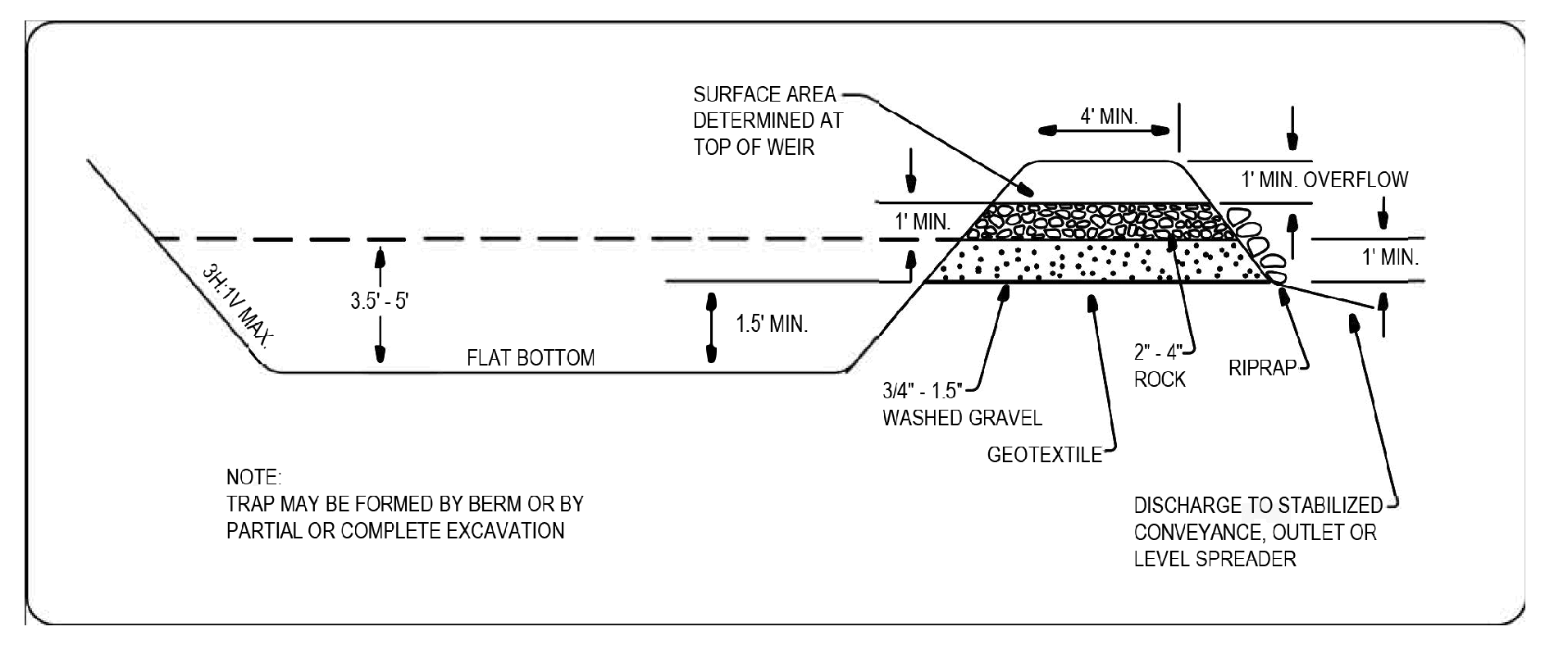
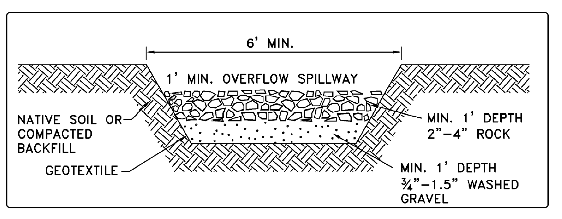
See Figure 3 - 27: Cross-Section of a Sediment Trap and Figure 3 - 28: Sediment Trap Outlet for details.
If permanent runoff control facilities are part of the project, they should be used for sediment retention.
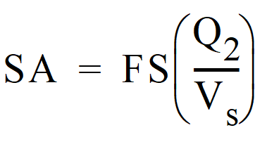
To determine the sediment trap geometry, first calculate the design surface area (SA) of the trap, measured at the invert of the weir. Use the following equation:
SA = Design surface area, in square feet, of the sediment trap measured at the invert of the weir.
Q2 = Design inflow, in cubic feet per second, is the peak volumetric flowrate from the contributing area calculated using a 10-minute timestep from a Type 1A, 2-year, 24-hour frequency storm using a single event model. A type 1A, 10-year, 24-hour frequency storm (Q10) shall be used in the calculation if the project size, expected timing and duration of construction, or downstream conditions warrant a higher level of protection. If no hydrologic analysis is required, the Rational Method may be used.
Q2 = Design inflow (cfs) is the 2-year return period flowrate, indicated by an Ecology-approved continuous simulation model, using an 15-minute timestep. Use the 10-year return period flowrate (Q10) in the calculation if the project size, expected timing and duration of construction, or downstream conditions warrant a higher level of protection.
Vs = The settling velocity of the soil particle of interest. The 0.02 millimeter (medium silt) particle with an assumed density of 2.65 grams per cubic centimeter has been selected as the particle of interest and has a settling velocity (Vs) of 0.00096 feet per second.
FS = A safety factor of 2 to account for non-ideal settling.
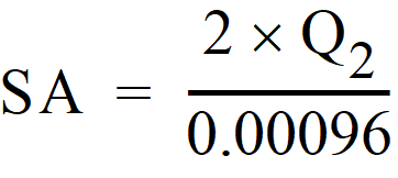
Therefore, the equation for computing surface area becomes:
Note: Even if permanent facilities are used, they must still have a surface area that is at least as large as that derived from the above formula. If they do not, the pond must be enlarged.
Smaller sites may use the minimum pond sizes in Table 3 - 15: Sediment Trap Sizing instead of providing calculations. Table 3 - 15: Sediment Trap Sizing
To aid in determining sediment depth, all sediment traps shall have a staff gauge with a prominent mark 1-foot above the bottom of the trap.
Sediment traps may not be feasible on utility projects due to the limited work space or short-term nature of the work. Portable tanks may be used in place of sediment traps for utility projects.
The basic geometry of the pond can now be determined using the following design criteria:
Required surface area SA (from the equation above) at top of riser.
Minimum 3.5-foot depth from top of riser to bottom of pond.
Maximum 3H:1V interior side slopes and maximum 2H:1V exterior slopes. The interior slopes can be increased to a maximum of 2H:1V if fencing is provided at or above the maximum water surface.
One foot of freeboard between the top of the riser and the crest of the emergency spillway.
Length-to-width ratio between 3:1 and 6:1.
Remove sediment from the trap when it reaches 1-foot in depth.
Repair any damage to the pond embankments or slopes.
Figure 3 - 27: Cross-Section of a Sediment Trap
Figure 3 - 28: Sediment Trap Outlet

 OR
OR
