Flow splitters are typically manholes or vaults with internal baffles, riser structures, or pipes designed to split off a portion of the main stormwater flow within the pipe. Flow splitters can be used in a variety of ways including:
Placing stormwater treatment facilities in an offline configuration so that only the water quality design flowrate reaches the facility.
Bypassing flows around a facility
Ensuring wetland hydrology is met,
The design of the flow splitter is dependent on the purpose of splitting the flows.
21.2.2 General Design Criteria
Comply with all criteria and standards in Modeling Your Best Management Practices, Design Criteria for All Stormwater Treatment and Flow Control BMPs, Constructing Your Best Management Practices and Accessing and Maintaining Your Best Management Practices as applicable to the project in addition to criteria within each BMP. Where criteria or standards conflict, utilize the criteria and standards contained within the specific BMP.
A flow splitter must be designed to deliver flowrates as necessary for the purpose of the flow splitter installation.
For stormwater facilities configured offline:
The flow splitter shall be designed to deliver the water quality design flowrate to the stormwater facility.
For baffle type flow splitting, the top of the weir shall be located at the water surface for the water quality design flowrate.
The maximum head must be minimized for flow in excess of the water quality design flowrate. At the 100-year water surface, the flowrate to the stormwater treatment facility cannot increase by more than 10%.
A backwater analysis of the existing or proposed conveyance system may be required by Environmental Services/Site Development Group per Joint Administrative Policy and Procedure Directive No. 2021-02-001.
Design flow splitters per Figure 4 - 54: Flow Splitter - Baffle Type and Figure 4 - 55: Flow Splitter - Riser Tee Type or provide an equivalent design.
Only baffle wall type flow splitters may be used for oil treatment BMPs.
As an alternative to using a solid top plate in Figure 4 - 55: Flow Splitter - Riser Tee Type, a full tee section may be used with the top of the tee at the 100-year water surface. This alternative would route emergency overflows (if the overflow pipe were plugged) through the WQ facility rather than back up from the maintenance hole.
Special applications, such as roads, may require the use of a modified flow splitter. The baffle wall may be fitted with a notch and adjustable weir plate to proportion runoff volumes other than high flows.
For ponding facilities, backwater effects must be considered in the design of the flow splitter.
Ladder or step and handhold access must be provided. If the weir wall is higher than 36 inches, two ladders, one to either side of the wall, must be used.
See A500 - Control Structures for orifice and weir design equations.
City of Tacoma owned flow splitters shall have concentric cones when feasible. Access shall be provided to the entire flow splitter for maintenance.
The splitter baffle may be installed in a Type 2 maintenance hole or vault.
The baffle wall must be made of reinforced concrete or another suitable material resistant to corrosion, and have a minimum 4-inch thickness. The minimum clearance between the top of the baffle wall and the bottom of the maintenance hole cover must be 4 feet; otherwise, dual access points shall be provided.
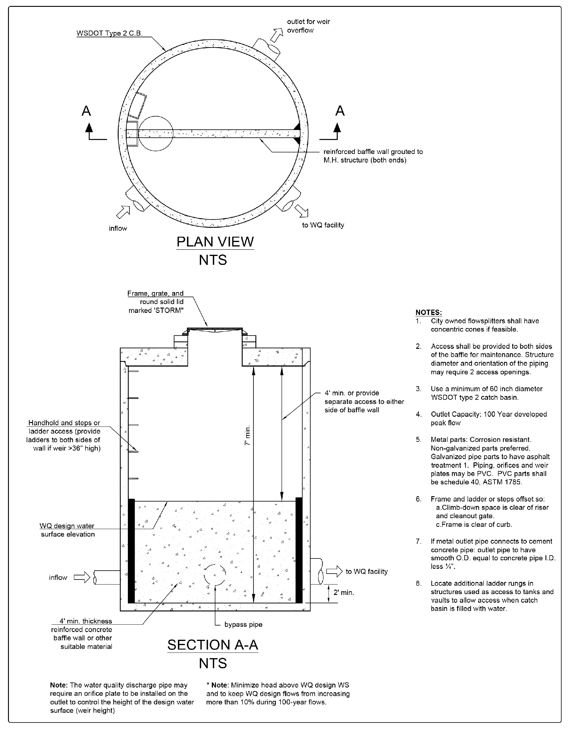
Figure 4 - 54: Flow Splitter - Baffle Type
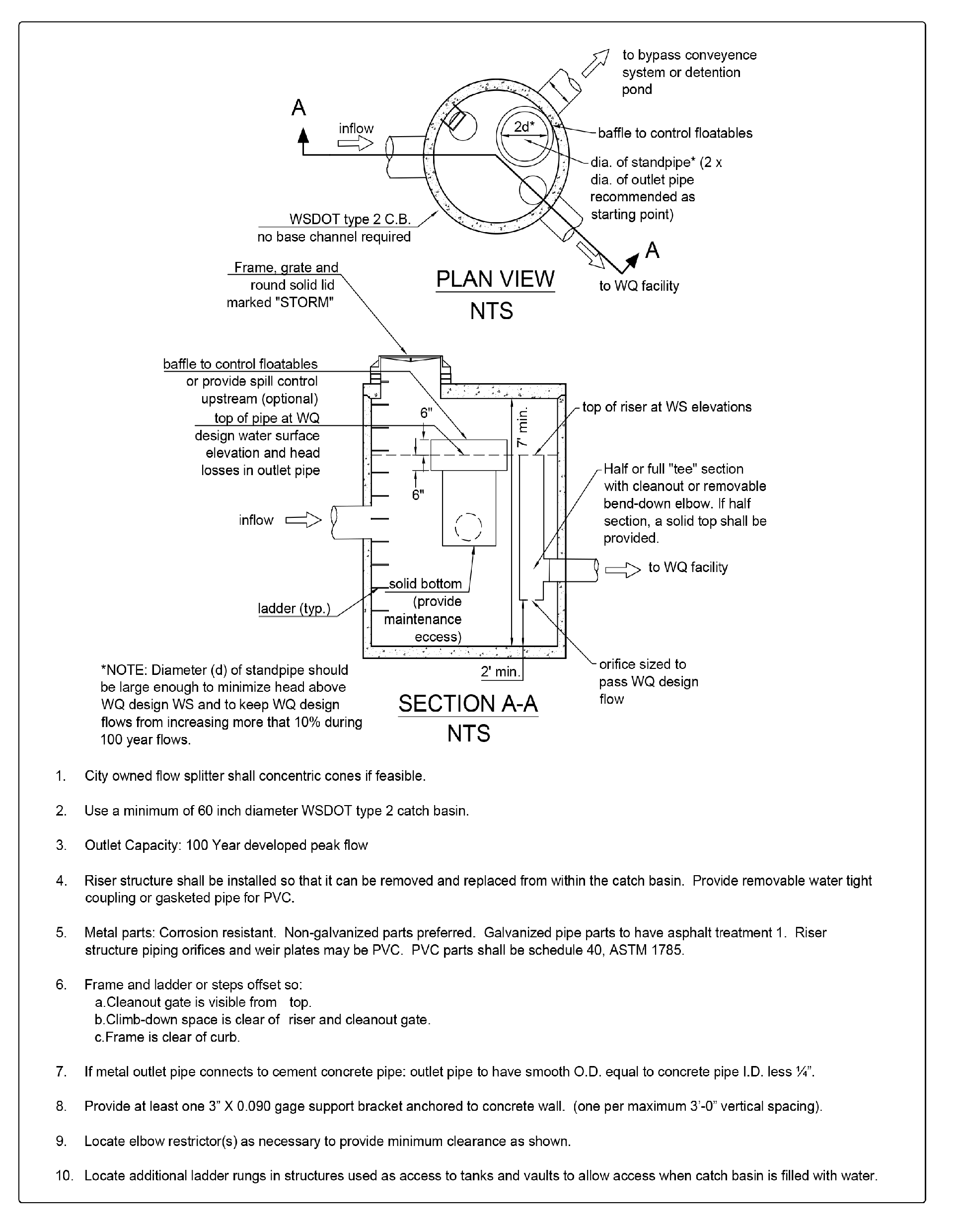
Figure 4 - 55: Flow Splitter - Riser Tee Type