8.1.6 BMP L602b - Downspout Infiltration Drywells
8.1.6.1 Design Criteria for Downspout Infiltration Drywells
Comply with all criteria and standards in Modeling Your Best Management Practices, Design Criteria for All Stormwater Treatment and Flow Control BMPs, Constructing Your Best Management Practices and Accessing and Maintaining Your Best Management Practices as applicable to the project in addition to criteria within each BMP. Where criteria or standards conflict, utilize the criteria and standards contained within the specific BMP.
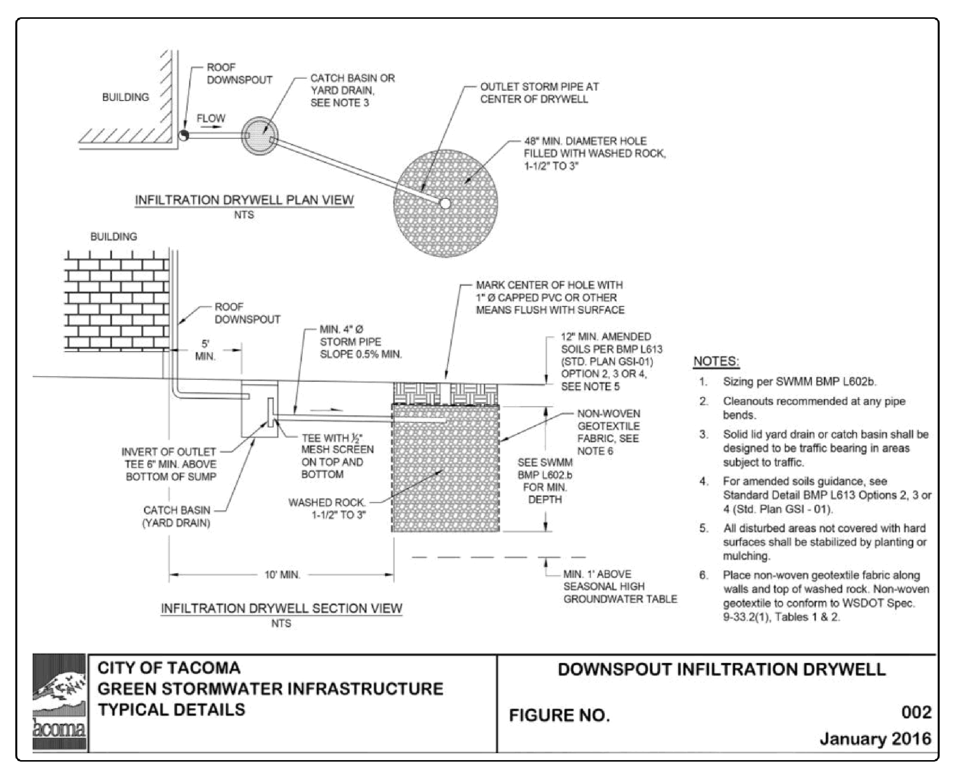
Figure 4 - 4: Typical Downspout Infiltration Drywell (also known as Green Stormwater Infrastructure Figure 002) shows a typical downspout infiltration drywell system. The applicant shall use this design in conjunction with the design criteria below.
A minimum of 1 foot of separation is required from the bottom of the drywell to the seasonal high groundwater table.
Drywells shall be 48 inches in diameter minimum and contain the washed rock volume specified below. The following minimum washed rock volumes per 1,000 square feet of roof areas based on soil type may be used for sizing the downspout dry well. For soil types other than those presented in Table 4 - 8: Downspout Infiltration Drywell Sizing Table, additional soils information and engineering analysis are required.
Table 4 - 8: Downspout Infiltration Drywell Sizing Table "Coarse Sand" - more than 50% of the sand fraction remains on #4 sieve "Medium Sand" - more than 50% of the sand fraction remains on the #40 sieve.
Washed rock shall be 1½ - 3” Washed Drain Rock with no fines.
Distribution pipe shall be a minimum 4" PVC pipe at 0.5% slope. The pipe shall end at the center of the drywell.
Mark the center of the drywell with a minimum 1" diameter PVC or other means flush with the surface.
Place a minimum 12" lawn or landscaped layer over the rock layer. The rock layer shall not extend to the surface.
All disturbed areas must be fully stabilized by planting and amended per BMP L613 - Post-Construction Soil Quality and Depth.
Non-woven geotextile fabric shall be placed on the sides of the drywell and over the drain rock prior to backfilling. Geotextile fabric shall not be placed on the bottom of the trench to avoid clogging. The non-woven geotextile shall conform to A2000 - Geotextile Specifications, Geotextile for Underground Drainage - Low Survivability, Class C.
Spacing between dry wells shall be a minimum of 10 feet, measured edge to edge.
Install a catch basin or yard drain upstream from the drywell.
Catch basin or yard drain shall have a minimum 6" sump depth below the tee.
The tee shall have a ½" mesh screen on top and bottom to capture large debris.
Catch basin or yard drain shall be traffic-bearing in areas subject to traffic.
8.1.7 Flow Credit for Roof Downspout Full Infiltration
If roof runoff is infiltrated according to the requirements of this section, the area contributing to the infiltration facility is not entered into an Ecology approved continuous simulation model. The area is still considered when determining project thresholds.
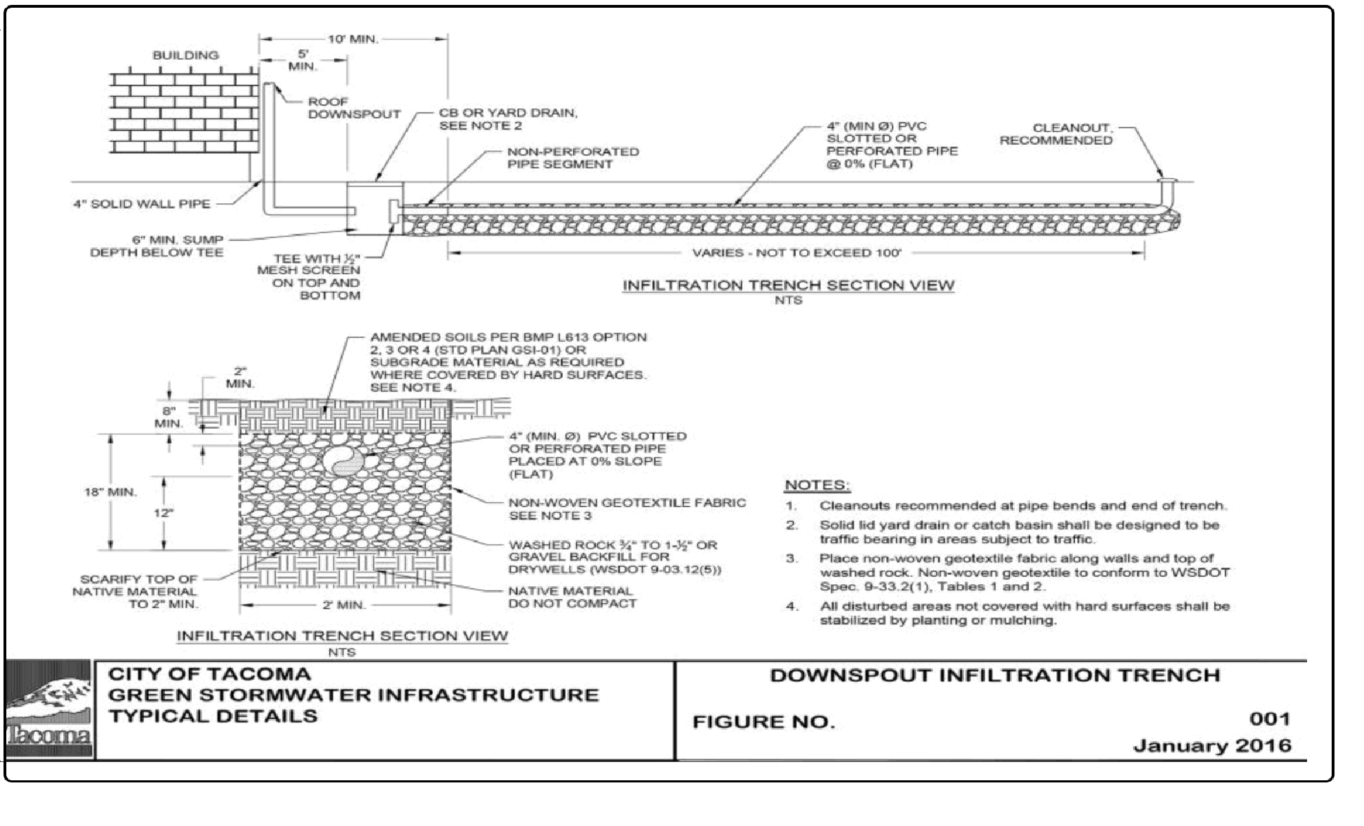
Figure 4 - 2: Typical Downspout Infiltration Trench
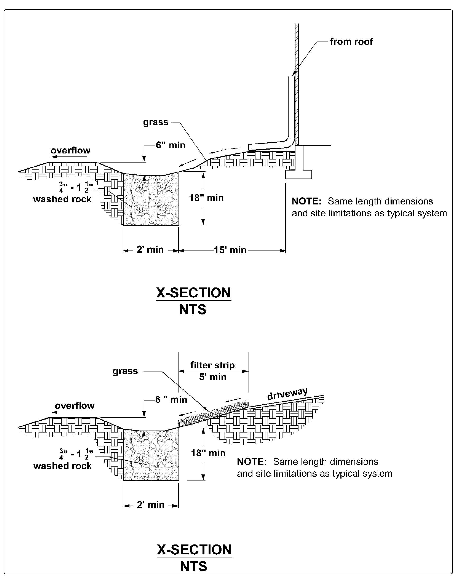
Figure 4 - 3: Alternative Infiltration Trench System for Coarse Sand and Gravel
Figure 4 - 4: Typical Downspout Infiltration Drywell


