4.3 Open Channel Specifications
Natural channels are defined as those that have occurred naturally due to the flow of surface waters, or those that, although originally constructed by human activity, have taken on the appearance of a natural channel including a stable route and biological community. They may vary hydraulically along each channel reach and should be left in their natural condition, wherever feasible or required, in order to maintain natural hydrologic functions and wildlife habitat benefits from established vegetation.
4.3.2 Constructed Channels
Constructed channels are those constructed or maintained by human activity and include bank stabilization of natural channels. Constructed channels shall be either vegetation-lined, rock lined, or lined with appropriately bioengineered vegetation.
Vegetation-lined channels are the most desirable of the constructed channels when properly designed and constructed. The vegetation stabilizes the slopes of the channel, controls erosion of the channel surface, and removes pollutants. The channel storage, low velocities, water quality benefits, and greenbelt multiple-use benefits create significant advantages over other constructed channels. The presence of vegetation in channels creates turbulence, which results in loss of energy and increased flow retardation; therefore, the design engineer must consider sediment deposition and scour, as well as flow capacity, when designing the channel. See A1000: Vegetation for examples of plants/seed mixes that may be appropriate for the vegetated channel.
Rock-lined channels are necessary where a vegetative lining will not provide adequate protection from erosive velocities. They may be constructed with riprap, gabions, or slope mattress linings. The rock lining increases the turbulence, resulting in a loss of energy and increased flow retardation. Rock lining also permits a higher design velocity and therefore a steeper design slope than in grass-lined channels. Rock linings are also used for erosion control at culvert and stormwater system outlets, sharp channel bends, channel confluences, and locally steepened channel sections.
Bioengineered vegetation lining is a desirable alternative to the conventional methods of rock armoring. Soil bioengineering is a highly specialized science that uses living plants and plant parts to stabilize eroded or damaged land. Properly designed bioengineering systems are capable of providing a measure of immediate soil protection and mechanical reinforcement. As the plants grow they produce vegetative protective cover and a root reinforcing matrix in the soil mantle. This root reinforcement serves several purposes:
The developed anchor roots provide both shear and tensile strength to the soil, thereby providing protection from the frictional shear and tensile velocity components to the soil mantle during the time when flows are receding and pore pressure is high in the saturated bank.
The root mat provides a living filter in the soil mantle that allows for the natural release of water after the high flows have receded.
The combined root system exhibits active friction transfer along the length of the living roots. This consolidates soil particles in the bank and serves to protect the soil structure from collapsing and the stabilization measures from failing.
4.3.3 Open Channel Design Criteria
Open channels shall be designed to provide required conveyance capacity while minimizing erosion and allowing for aesthetics, habitat preservation, and enhancement. See Section 3.4.4 Open Channel Design Events for open channel sizing criteria.
An access easement for maintenance is required along all constructed channels located on private property. Required easement widths and building setback lines vary with channel top width.
Channel cross-section geometry shall be trapezoidal, triangular, parabolic, or segmental. Side slopes shall be no steeper than 3:1 for vegetation-lined channels and 2:1 for rock-lined channels.
Vegetation-lined channels shall have bottom slope gradients of 6% or less and a maximum velocity at design flow of 5 fps (see Table 5 - 6: Channel Protection).
Rock-lined channels or bank stabilization of natural channels shall be used when design flow velocities exceed 5 feet per second. Rock stabilization shall be in accordance with Table 5 - 6: Channel Protection or stabilized with bioengineering methods as described above in Constructed Channels.
4.3.4 Open Channel Stabilization
Open channels must be protected to avoid channel erosion. Table 5 - 6: Channel Protection describes protection types based upon velocity in the channel. Table 5 - 6: Channel Protection (1) Rock Lining shall be reasonable well graded as follows: Note: Riprap sizing is governed by side slopes on channel, assumed to be approximately 3:1.
4.3.4.2 Riprap Design1
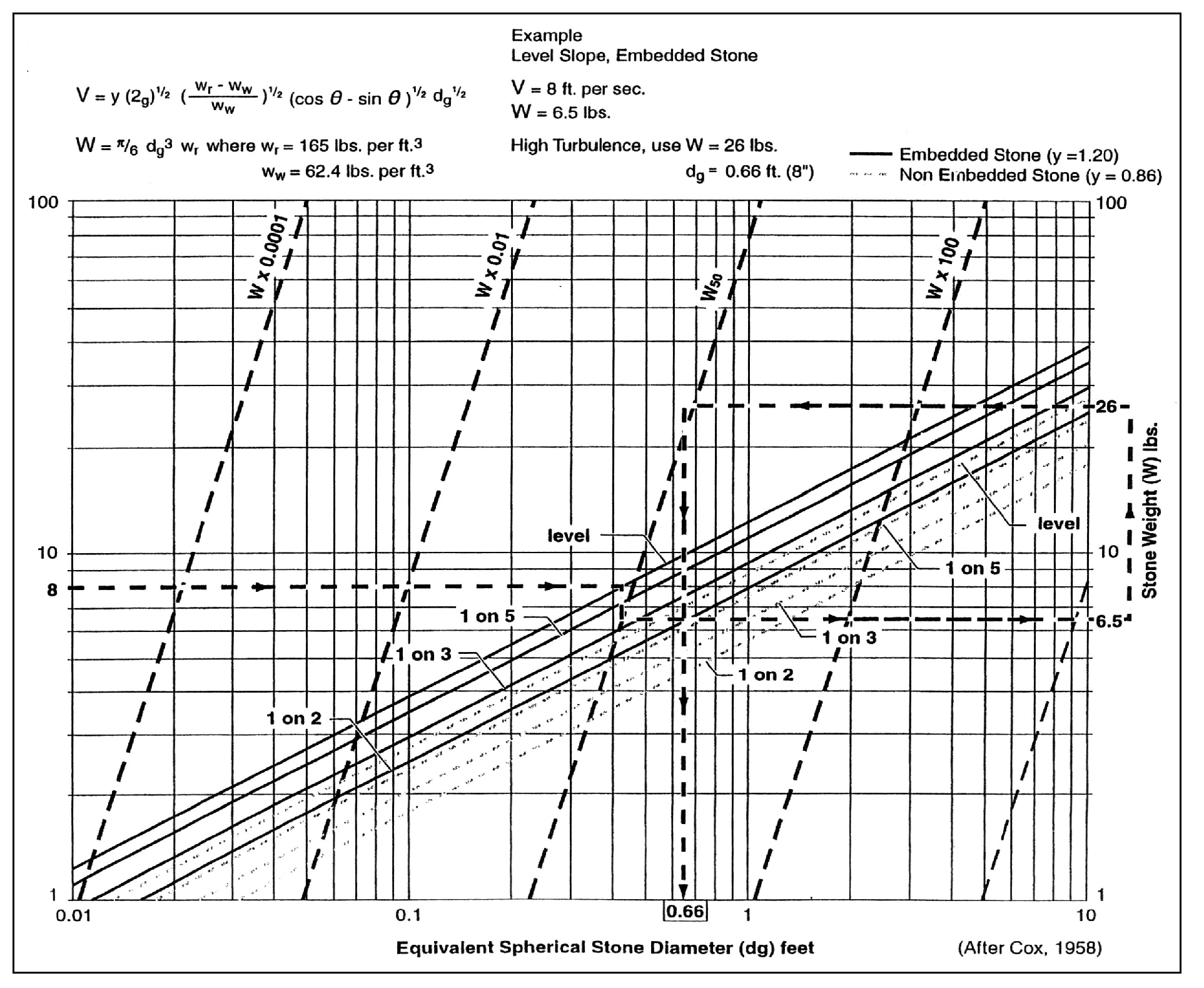
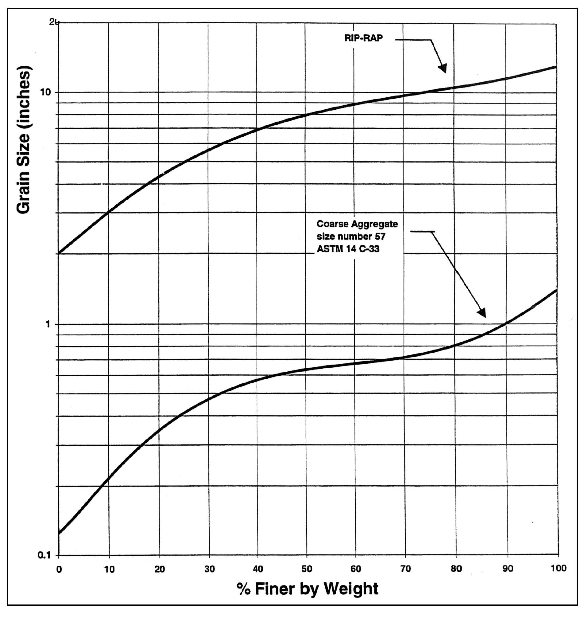
Proper riprap design requires the determination of the median size of stone, the thickness of the riprap layer, the gradation of stone sizes, and the selection of angular stones, which will interlock when placed. Research by the U.S. Army Corps of Engineers has provided criteria for selecting the median stone weight, W50 (Figure 5 - 4: Mean Channel Velocity vs Medium Stone Weight (W50) and Equivalent Stone Diameter). If the riprap is to be used in a highly turbulent zone (such as at a culvert outfall, downstream of a stilling basin, at sharp changes in channel geometry, etc.), the median stone W50 should be increased from 200% to 600% depending on the severity of the locally high turbulence. The thickness of the riprap layer should generally be twice the median stone diameter (D50) or at least equivalent to the diameter of the maximum stone. The riprap should have a reasonably well-graded assortment of stone sizes within the following gradation:
Riprap should be underlain by a sand and gravel filter (or filter fabric) to keep the fine materials in the underlying channel bed from being washed through the voids in the riprap. Likewise, the filter material must be selected so that it is not washed through the voids in the riprap. Adequate filters can usually be provided by a reasonably well graded sand and gravel material where:
The variable d85 refers to the sieve opening through which 85% of the material being protected will pass, and D15 has the same interpretation for the filter material. A filter material with a D50 of 0.5 mm will protect any finer material including clay. Where very large riprap is used, it is sometimes necessary to use two filter layers between the material being protected and the riprap.
What embedded riprap design should be used to protect a streambank at a level culvert outfall where the outfall velocities in the vicinity of the downstream toe are expected to be about 8 fps.
From Figure 5 - 4: Mean Channel Velocity vs Medium Stone Weight (W50) and Equivalent Stone Diameter, W50 = 6.5 lbs, but since the downstream area below the outfall will be subjected to severe turbulence, increase W50 by 400% so that:
W50 = 26 lbs, D50 = 8.0 inches
The gradation of the riprap is shown in Figure 5 - 5: Riprap Gradation Curve, and the minimum thickness would be 1 foot (from Table 5 - 6: Channel Protection); however, 16 inches to 24 inches of riprap thickness would provide some additional insurance that the riprap will function properly in this highly turbulent area.
Figure 5 - 5: Riprap Gradation Curve shows that the gradation curve for ASTM C33, size number 57 coarse aggregate (used in concrete mixes), would meet the filter criteria. Applying the filter criteria to the coarse aggregate demonstrates that any underlying material whose gradation was coarser than that of concrete sand would be protected.
For additional information and procedures for specifying filters for riprap, refer to the Army Corps of Engineers Manual EM 1110-2-1601, Hydraulic Design of Flood Control Channels, Paragraph 14, “Riprap Protection.”
Figure 5 - 4: Mean Channel Velocity vs Medium Stone Weight (W50) and Equivalent Stone Diameter
Figure 5 - 5: Riprap Gradation Curve

