This section presents the methods, criteria and details for analysis and design of outfall systems. Properly designed outfalls are critical to reducing the chance of adverse impacts as the result of concentrated discharges from pipe systems and culverts, both onsite and downstream. Outfall systems include piping, rock splash pads, flow dispersal trenches, gabion or other energy dissipaters.
21.4.1 Outfall Design Criteria
Comply with all criteria and standards in Modeling Your Best Management Practices, Design Criteria for All Stormwater Treatment and Flow Control BMPs, Constructing Your Best Management Practices and Accessing and Maintaining Your Best Management Practices as applicable to the project. Where criteria or standards conflict, utilize the criteria and standards contained within the specific BMP.
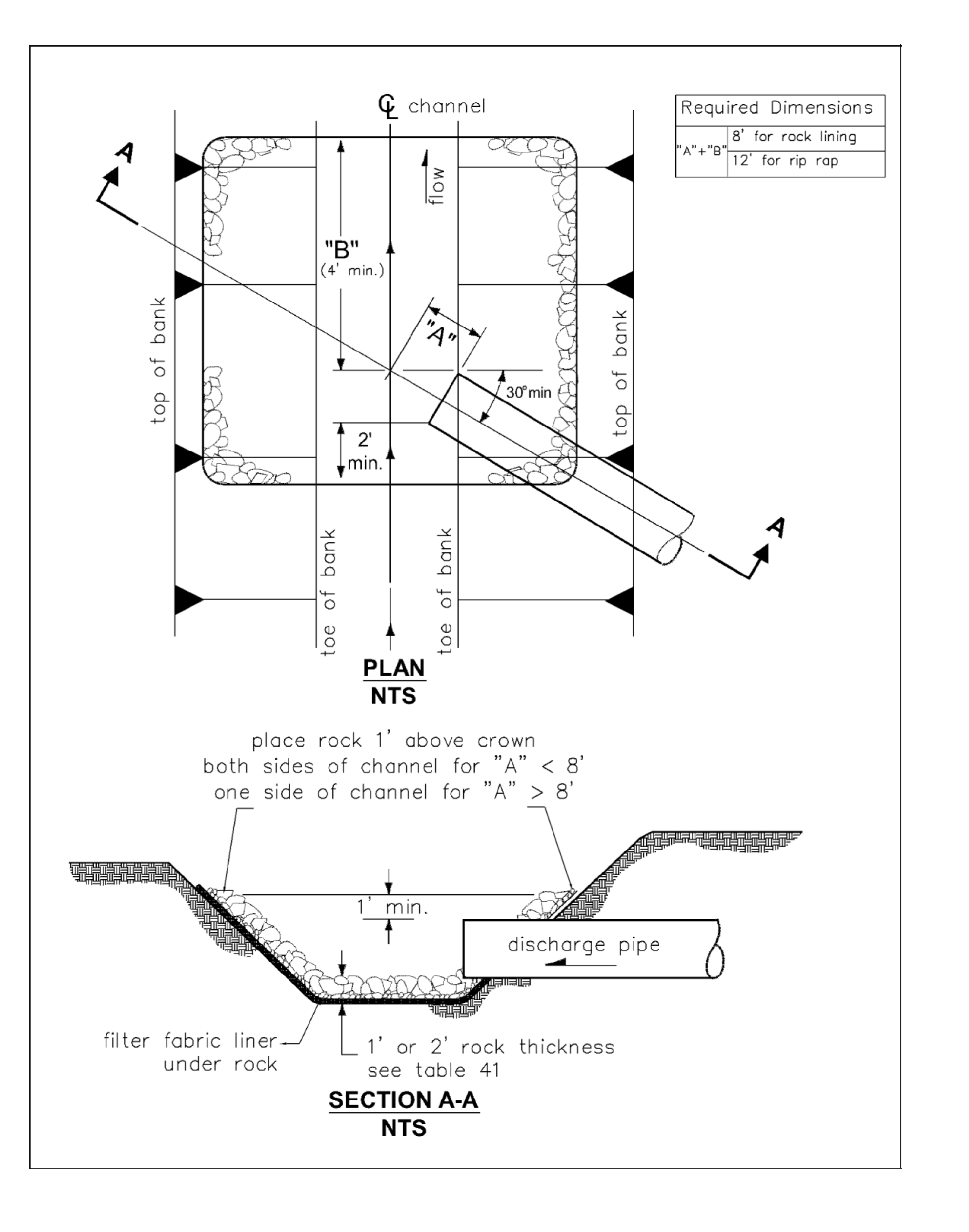
All outfalls must be provided with an appropriate outlet / energy dissipation structure such as a dispersal trench, gabion outfall, or rock splash pad (see Figure 4 - 60: Pipe/Culvert Outfall Discharge Protection) as specified below and in .
No erosion or flooding of downstream properties shall result from discharge from an outfall.
State, federal and local permits are required for work near or within receiving waters. See https://www.oria.wa.gov/site/alias__oria/permitting_our_permitting_services/347/our_permitting_services.aspx for information about potential State and Federal Permits that may be required. See tacomapermits.org for information on the types of City of Tacoma permits that may need to be obtained when installing an outfall system.
Outfall structures should be located where they minimize impacts to fish, shellfish, and their habitat.
Energy dissipaters shall be located above the Ordinary High Water Mark on fish bearing streams. Outfalls not intended for fish passage shall have an invert elevation a minimum of 1' above the Ordinary High Water Mark.
Bank stabilization, bioengineering, and habitat features may be required for disturbed areas.
Rock splash pads and gabion structures are not recommended due to corrosion and destruction of the structure, particularly in high energy environments.
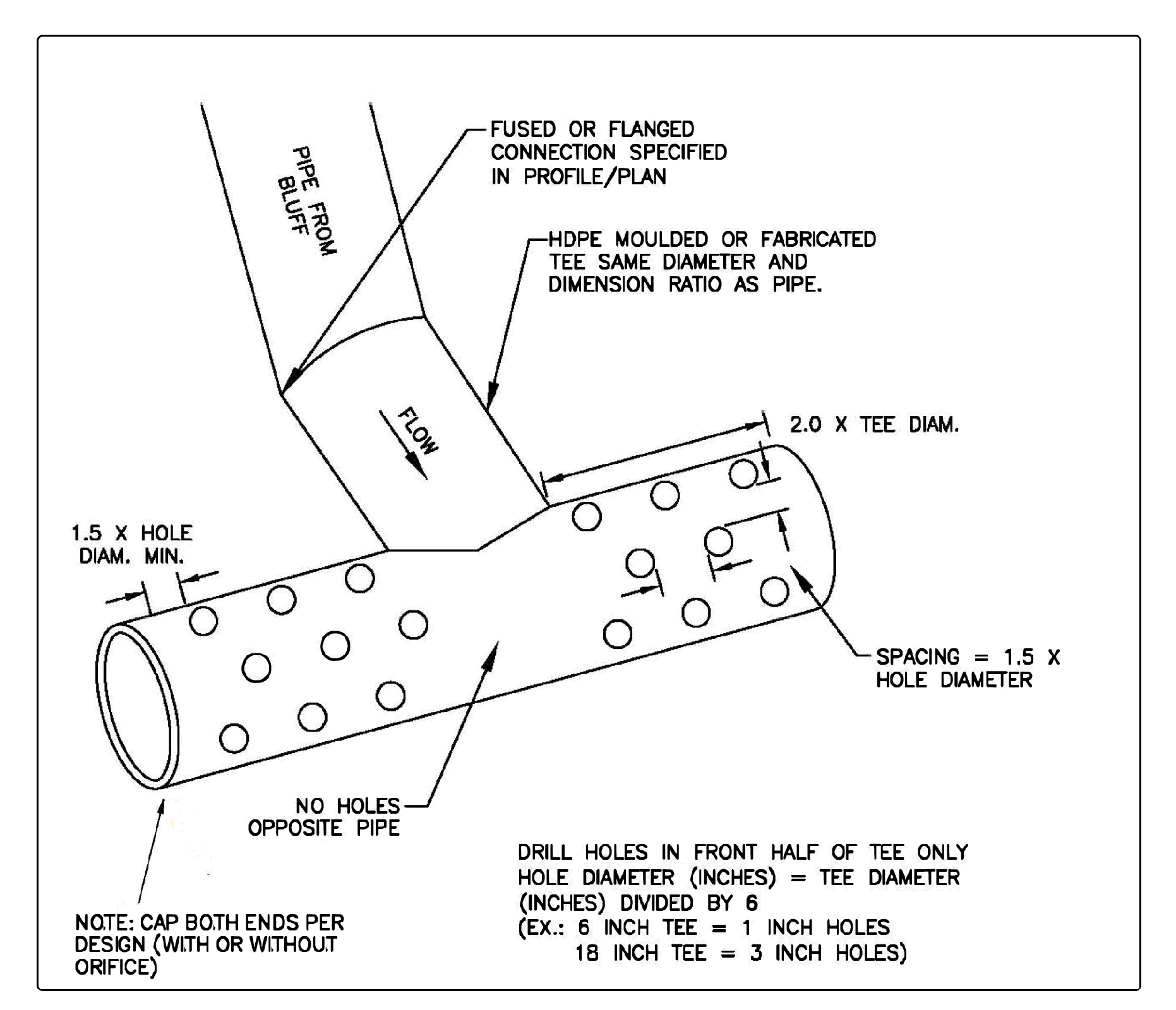
Diffuser Tee structures, such as shown in Figure 4 - 64: Diffuser Tee, are not recommended in or above the intertidal zone though they may be acceptable in low bank or rock shoreline locations.
Piped conveyance systems trenched to extreme low water or dissipation above the high water line are preferred.
Outfalls below extreme low water may still need an energy dissipation device to prevent erosion in the immediate vicinity of the discharge.
Stormwater outfalls submerged in a marine environment are subject to plugging due to biological growth and shifting debris and sediment. Regular maintenance is needed to ensure outfall can function as designed.
Gabion outfall and engineered energy dissipater shall be designed by a Washington State Licensed Professional Engineer. The basis for design and accompanying calculations shall be include in the signed and stamped Stormwater Site Plan Report.
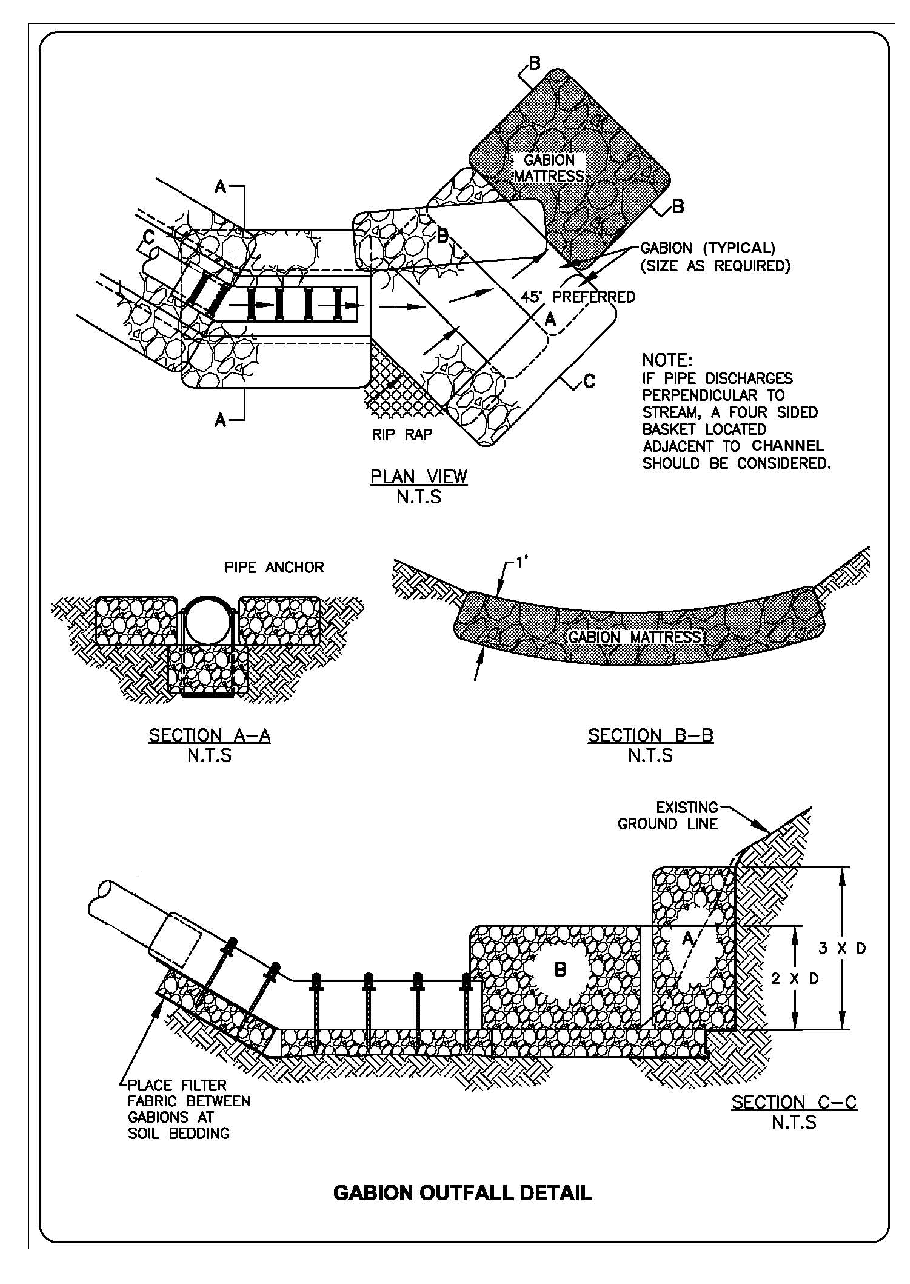
Gabion outfalls are required when the design velocity is greater than 10 ft/s.
The gabion outfall detail shown in Figure 4 - 63: Gabion Outfall Detail is for illustrative purposes only. A site specific detail is needed for all gabion outfalls.
The in-stream sample gabion mattress may not be acceptable within the ordinary high water mark of fish-bearing waters or where gabions will be subject to abrasion from upstream channel sediments. A four-sided basion basket located outside the ordinary high water mark should be considered for these applications.
Engineered energy dissipaters, such as stilling basins, drop pools, hydraulic jump basins, baffled aprons, and bucket aprons area required when the design velocity is greater than 20 ft/s.
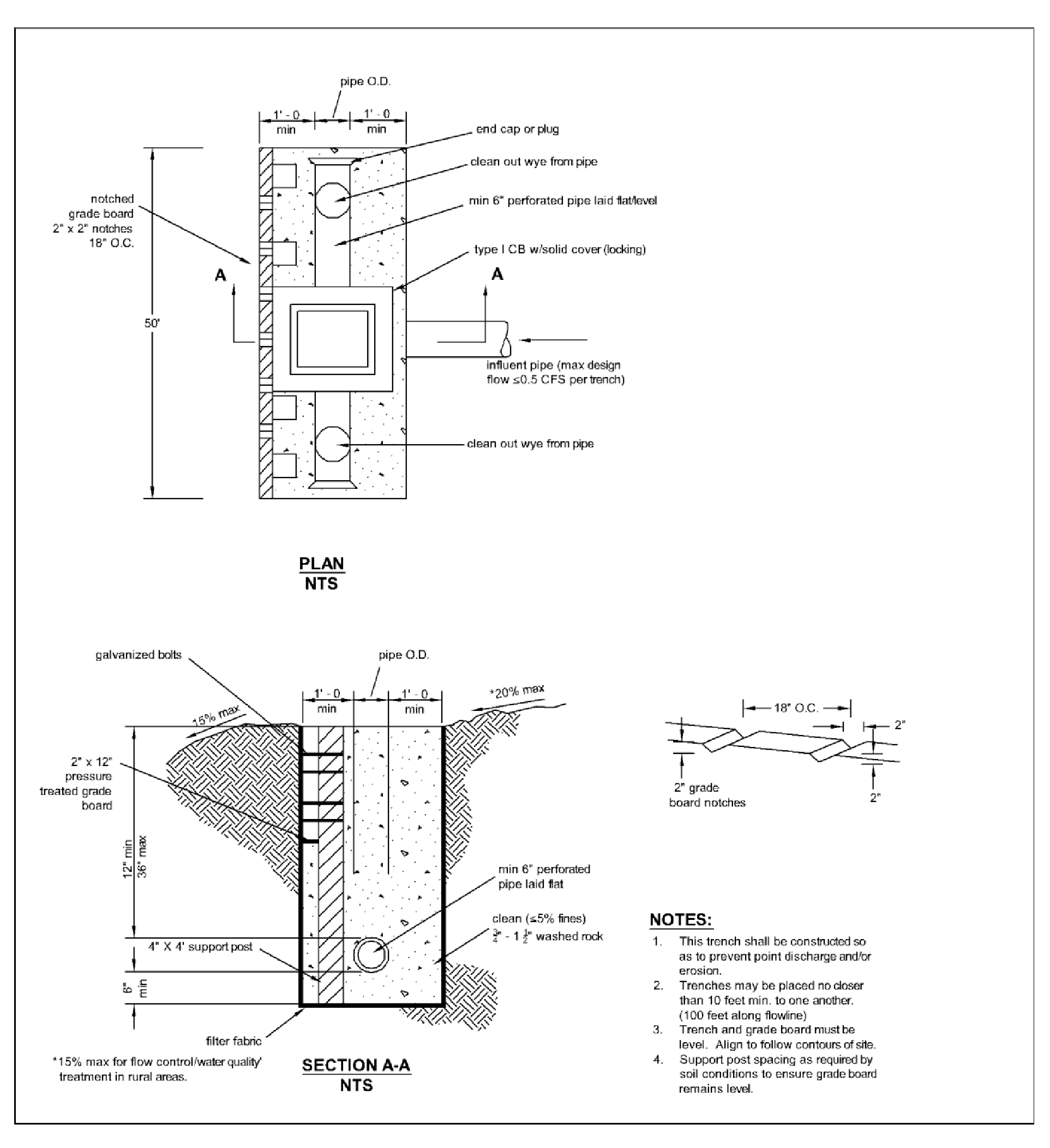
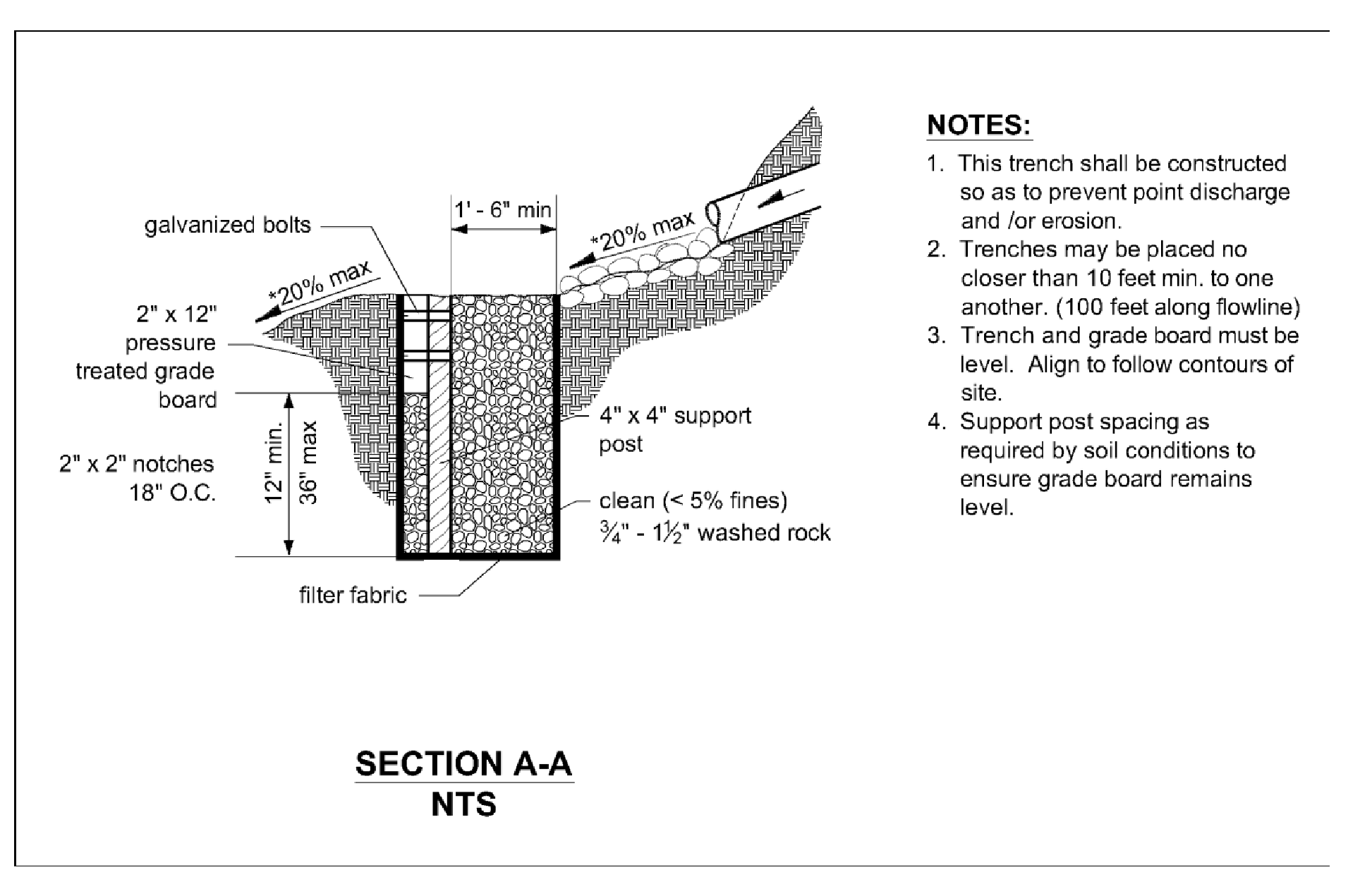
The flow dispersion trenches shown in Figure 4 - 61: Flow Dispersal Trench and Figure 4 - 62: Alternative Flow Dispersal Trench, shall only be used when both criteria are met:
An outfall is necessary to disperse concentrated flows across uplands where no conveyance system exists and the natural (existing) discharge is unconcentrated; and
The 100-year peak discharge rate is less than or equal to 0.5 cfs.
Alternative outfall protection may be used provided the design is based on sound hydraulic principles and ease of construction and maintenance. A Washington State Licensed Professional Engineer shall design the alternative measure. The basis for design and accompanying calculations shall be include in the signed and stamped Stormwater Site Plan Report.
Piped conveyance systems (tightline systems) shall:
Be designed by a Washington State Licensed Professional Engineer.
Use the appropriate pipe type and fittings for the situation.
Consider the need for thermal expansion and contraction.
Be buried to a depth sufficient to avoid exposure of the pipe during storm events and changes in beach elevation. If non-native material is used to bed the pipe, the material must be covered with at least 3 feet of native bed or equivalent.
Consider the need for pipe anchoring based on pipe material and location characteristics. See Volume 5 for additional information.
Mechanisms that reduce velocity prior to discharge from an outfall are encouraged. Some of these are drop manholes and rapid expansion into pipes of much larger size. Other discharge end features may be used to dissipate the discharge energy. An example of an end feature is the use of a Diffuser Tee with holes in the front half, as shown in Figure 4 - 64: Diffuser Tee.
Figure 4 - 60: Pipe/Culvert Outfall Discharge Protection
Figure 4 - 61: Flow Dispersal Trench
Figure 4 - 62: Alternative Flow Dispersal Trench
Figure 4 - 63: Gabion Outfall Detail
Figure 4 - 64: Diffuser Tee
