21.5 A500 - Control Structures
Control structures are catch basins or manholes with a restrictor device for controlling outflow from a facility to meet the desired performance.
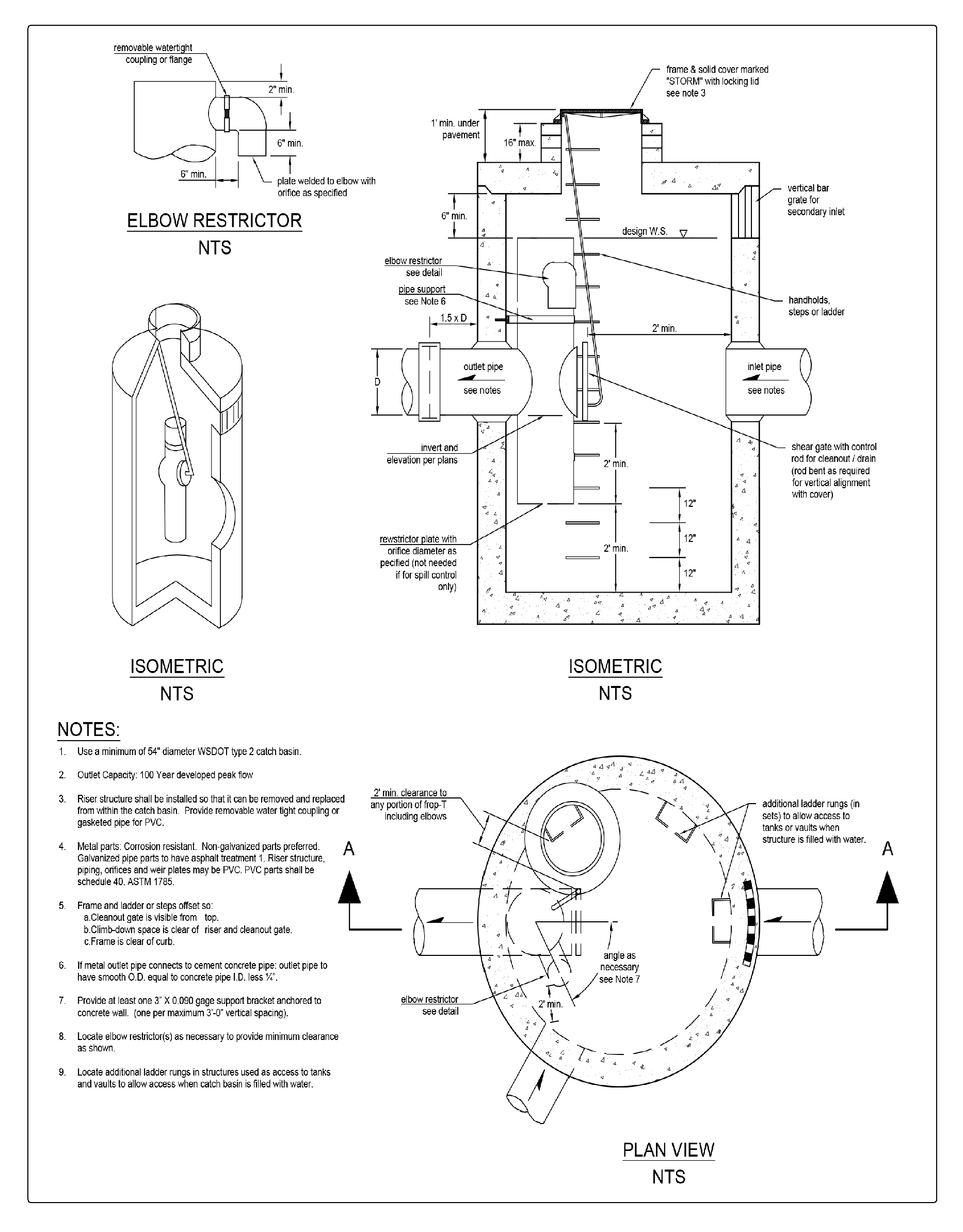
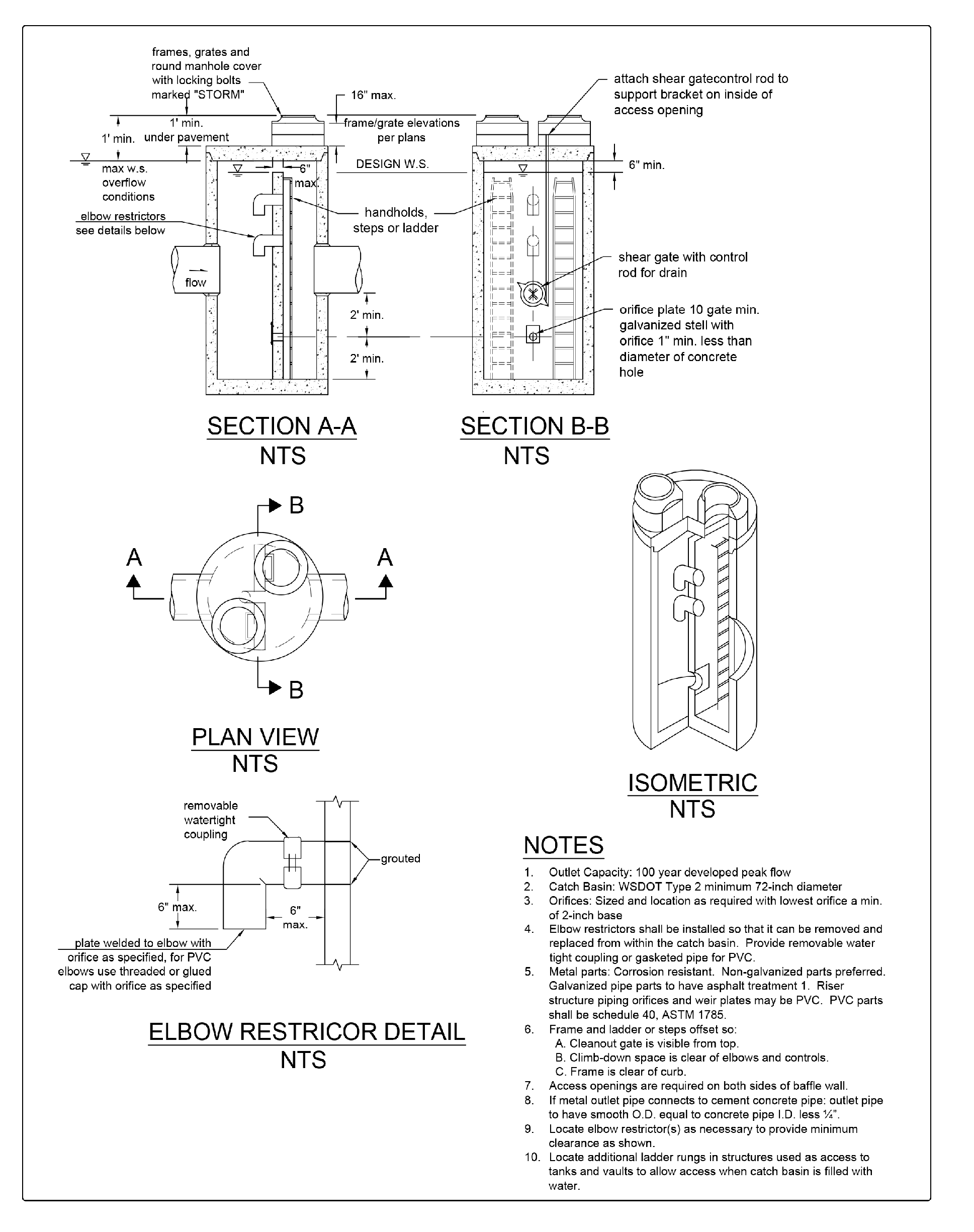
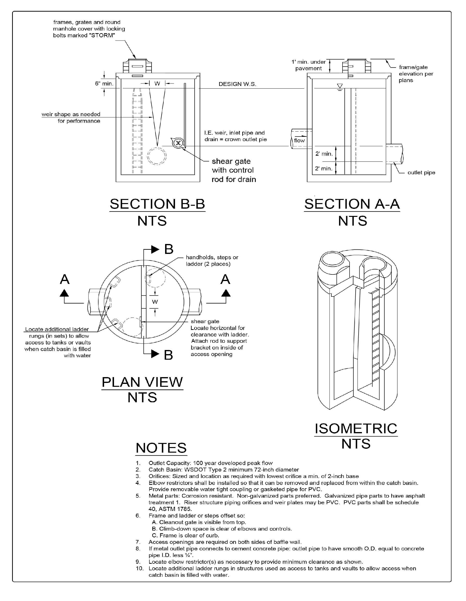
The restrictor device usually consists of two or more orifices and/or a weir section sized to meet performance requirements. Standard control structure details are shown in Figure 4 - 65 through Figure 4 - 72.
Comply with all criteria and standards in Modeling Your Best Management Practices, Design Criteria for All Stormwater Treatment and Flow Control BMPs, Constructing Your Best Management Practices and Accessing and Maintaining Your Best Management Practices as applicable to the project in addition to criteria within each BMP. Where criteria or standards conflict, utilize the criteria and standards contained within the specific BMP.
21.5.2.1 Multiple Orifice Restrictor
In most cases, control structures need only two orifices: one at the bottom and one near the top of the riser, although additional orifices may best utilize detention storage volume. Several orifices may be located at the same elevation if necessary to meet performance requirements.
Minimum orifice diameter is 0.5 inches. In some instances, a 0.5-inch bottom orifice will be too large to meet target release rates, even with minimal head. In these cases, do not reduce the live storage depth to less than 3 feet in an attempt to meet the performance standards. Under such circumstances, flow-throttling devices may be a feasible option. These devices will throttle flows while maintaining a plug-resistant opening.
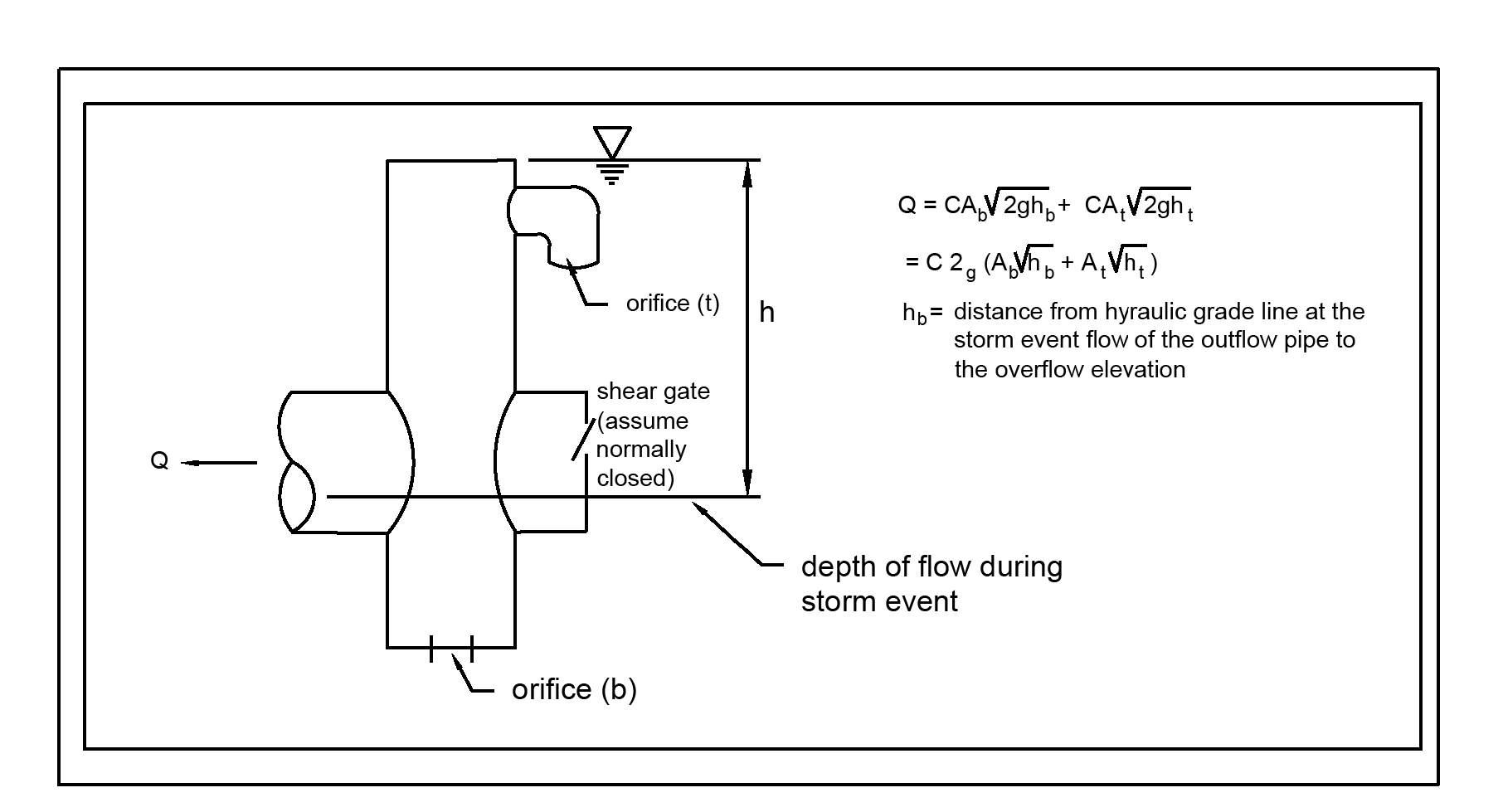
Orifices may be constructed on a tee section as shown in Figure 4 - 65: Flow Restrictor (TEE) or on a baffle as shown in Figure 4 - 66: Flow Restrictor (Baffle).
In some cases, performance requirements may require the top orifice/elbow to be located too high on the riser to be physically constructed (e.g. a 13-inch diameter orifice positioned 0.5 feet from the top of the riser). In these cases, a notch weir in the riser pipe may be used to meet performance requirements (see Figure 4 - 67: Flow Restrictor (Weir)).
Backwater effects from water surface elevations in the conveyance system shall be evaluated. High tailwater elevations may affect performance of the restrictor system and reduce live storage volumes. Backwater effects shall also be analyzed for areas that are influenced by tides.
21.5.2.2 Riser and Weir Restrictor
Properly designed weirs may be used as flow restrictors (see Figure 4 - 68 and Figure 4 - 70 through Figure 4 - 71). However, they must be designed to provide for primary overflow of the developed 100-year peak flow discharging to the detention facility.
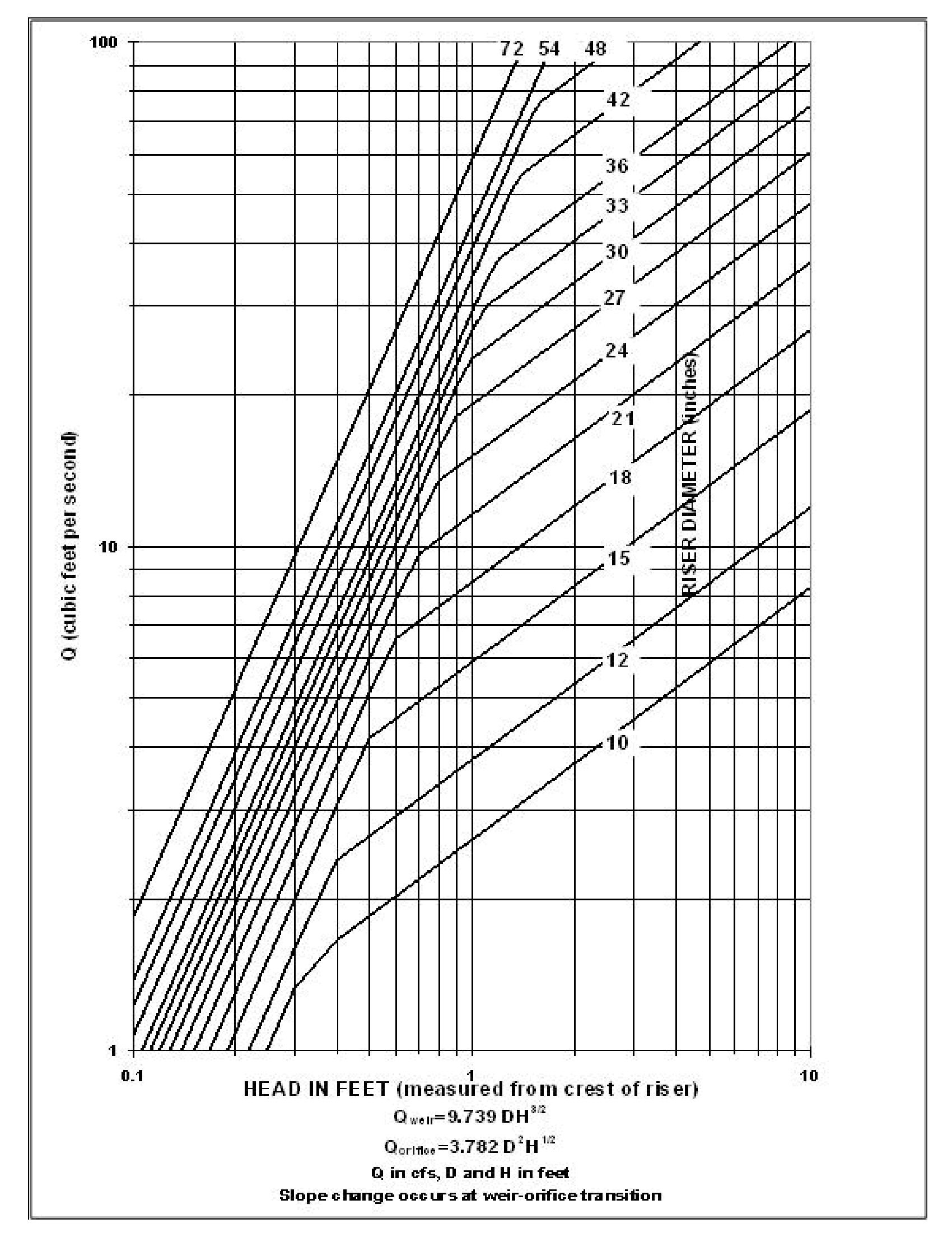
The combined orifice and riser (or weir) overflow may be used to meet performance requirements. However, the design must still provide for primary overflow of the developed peak volumetric flowrate calculated using a 10-minute timestep from a Type 1A, 100-year, 24-hour frequency storm using a single event model or 100-year return period flowrate, indicated by an Ecology-approved continuous simulation model, using a 15-minute timestep, assuming all orifices are plugged. Figure 4 - 72: Riser Inflow Curves can be used to calculate the head in feet above a riser of given diameter and flow.
An access road to the control structure is needed for inspection and maintenance, and must be designed and constructed as specified in A3000 - Access Ramps and Roads.
Maintenance hole and catch basin lids for control structures must be locking, and rim elevations must match proposed finish grade.
Manholes and catch basins must meet the OSHA confined space requirements, which include clearly marking entrances to confined space areas.
Acceptable materials for stormwater facilities include thermoplastics, iron, steel, aluminum, and concrete. Steel and iron shall be aluminum coated (aluminized Type 2). Zinc coated (galvanized) materials are prohibited. Painted metal parts shall not be used because of poor longevity.
This section presents the methods and equations for design of control structure restrictor devices. Included are details for the design of orifices, rectangular sharp-crested weirs, v-notch weirs, sutro weirs, and overflow risers.
Flow-through orifice plates in the standard tee section or turn-down elbow may be approximated by the general equation:
Q = flow (cfs)
C = coefficient of discharge (0.62 for plate orifice)
A = area of orifice (ft2)
h = hydraulic head (ft)
g = gravity (32.2 ft/sec2)
Figure 4 - 68: Simple Orifice illustrates this simplified application of the orifice equation.
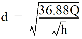
The diameter of the orifice is calculated from the flow. The orifice equation is often useful when expressed as the orifice diameter in inches:
d = orifice diameter (inches)
Q = flow (cfs)
h = hydraulic head (ft)
21.5.3.2 Rectangular Sharp-Crested Weir
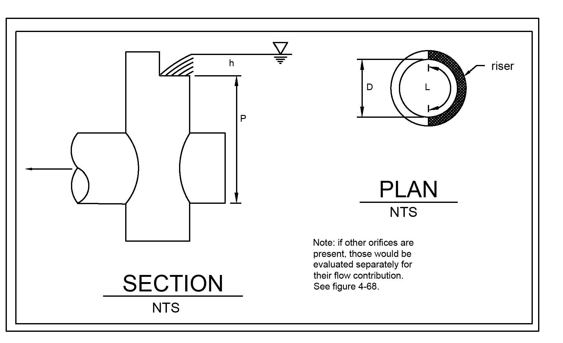
The rectangular sharp-crested weir design shown in Figure 4 - 69: Rectangular, Sharp-Crested Weir may be analyzed using standard weir equations for the fully contracted condition. The Francis Formula is shown below and requires use of Imperial units.
Q = flow (cfs)
C = 3.27 + 0.40 h/P (ft)
h, P = as shown in Figure 4 - 69: Rectangular, Sharp-Crested Weir
L = length (ft) of the portion of the riser circumference as necessary not to exceed 50 percent of the circumference
D = inside riser diameter (ft)
Note: This equation accounts for side contractions by subtracting 0.1h from L for each side of the notch weir.
21.5.3.3 V-Notch Sharp-Crested Weir
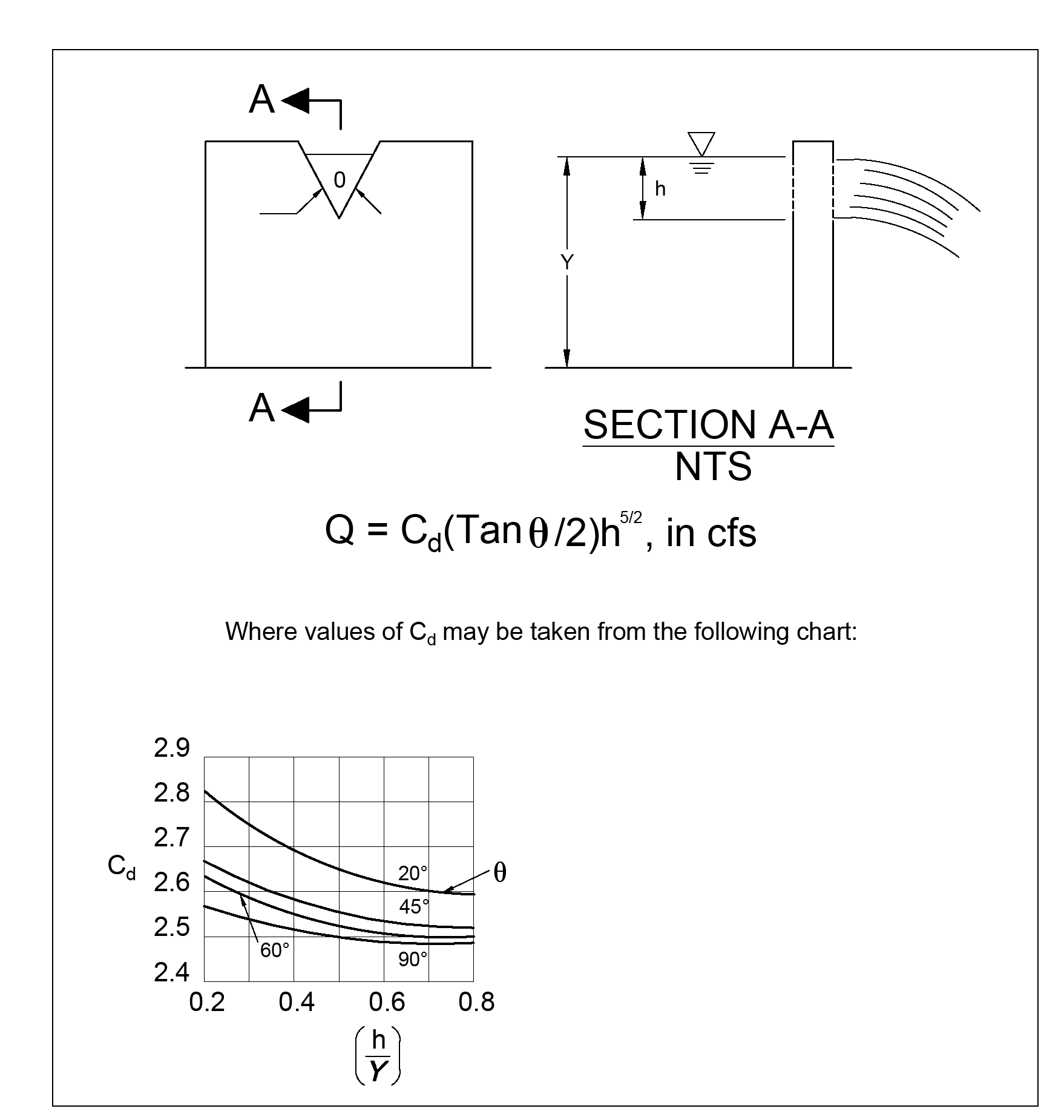
V-notch weirs as shown in Figure 4 - 70: V-Notch, Sharp-Crested Weir may be analyzed using standard equations for the fully contracted condition.
21.5.3.4 Proportional or Sutro Weir
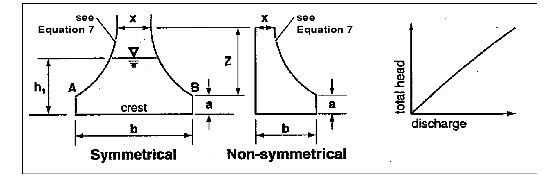
Sutro weirs are designed so that the discharge is proportional to the total head. This design may be useful in some cases to meet performance requirements.
The sutro weir consists of a rectangular section joined to a curved portion that provides proportionality for all heads above the line A-B (see Figure 4 - 71: Sutro Weir). The weir may be symmetrical or non-symmetrical.
For this type of weir, the curved portion is defined by the following equation (calculated in radians):
a, b, x and Z are as shown in Figure 4 - 71: Sutro Weir.
The head-discharge relationship is:
Values of Cd for both symmetrical and non-symmetrical sutro weirs are summarized in Table 4 - 30: Values of Cd for Sutro Weirs; h1 is shown in Figure 4 - 71: Sutro Weir.
When b > 1.50 or a > 0.30, use Cd=0.6.
The nomograph in Figure 4 - 72: Riser Inflow Curves can be used to determine the head (in feet) above a riser of given diameter and for a given flow (usually the 100-year peak flow for developed conditions).
Note: Q100 is either the peak 10-minute flow computed from the 100-year, 24-hour storm and a Type 1A distribution, or the 100-year return period flowrate as estimated by an Ecology approved continuous simulation model assuming 15-minute timesteps.
Table 4 - 30: Values of Cd for Sutro Weirs
Figure 4 - 65: Flow Restrictor (TEE)
Figure 4 - 66: Flow Restrictor (Baffle)
Figure 4 - 67: Flow Restrictor (Weir)
Figure 4 - 68: Simple Orifice
Figure 4 - 69: Rectangular, Sharp-Crested Weir
Figure 4 - 70: V-Notch, Sharp-Crested Weir
Figure 4 - 71: Sutro Weir
Figure 4 - 72: Riser Inflow Curves

