8.3 BMP L604 - Perforated Stub-Out Connections
A perforated stub-out connection is a length of perforated pipe within a washed rock-filled trench that is placed between roof downspouts and a stub-out to the City stormwater system. These systems are intended to provide some infiltration during drier months. During the wet winter months, they may provide little or no flow control.
This BMP can be utilized to ensure compliance with Minimum Requirement 5 - Onsite Stormwater Management.
Where compliance with Minimum Requirements is not required, where feasible, this BMP is recommended to be used to help protect receiving waterbodies from the effects of stormwater.
8.3.3 Infeasibility Criteria for Perforated Stub-Out Connections
The following infeasibility criteria describe conditions that make perforated stub-out connections infeasible when applying The List Approach for compliance with Minimum Requirement 5 - Onsite Stormwater Management.
The infeasibility criteria shall also be used to determine the appropriateness of installing perforated stub-outs on a project site. Project proponents may be allowed to install perforated stub-outs even if considered infeasible, unless otherwise stated within the specific infeasibility criteria, provided documentation is included that substantiates the design. Documentation may be required by a Washington State Licensed Professional Engineer or other appropriate professional depending on the project conditions.
A site characterization study is required to determine infeasibility and to determine the appropriateness of installing Perforated Stub-Outs.
The setback criteria and design standards cannot be met.
The depth from the bottom of the trench to the seasonal high groundwater table or other impermeable layer is less than one foot. Citation of this infeasibility criterion requires evaluation of site specific conditions and a soils report.
If there are any conflicts with any of the following competing needs criteria:
Requirements of the following federal or state laws, rules, and standards:
Historic Preservation Laws and Archaeology Laws as listed at: https://dahp.wa.gov/project-review/preservation-laws
Federal Superfund or Washington State Model Toxics Control Act
Federal Aviation Administration requirements for airports
American with Disabilities Act
When found to be in conflict with special zoning district design criteria adopted and being implemented pursuant to a community planning process.
Public health and safety standards
Transportation regulations to maintain the option for future expansion or multi-modal use of public rights-of-way.
City of Tacoma Critical Area Ordinances that provides protection of tree species or other critical areas.
The following are minimum setbacks:
At least 10 feet from any building structure and at least 5 feet from any other structure or property line unless approved in writing by Environmental Services/Site Development Group per Joint Administrative Policy and Procedure Directive No. 2021-02-001.
Perforated pipe systems shall be setback a minimum of 50 feet from the top of any slope greater than 20% and from geologically hazardous areas. The perforated pipe system may be sited within 50 feet of a slope greater than 20% and/or geologically hazardous area if a geotechnical analysis performed by a Washington State Licensed Professional Engineer or Washington State Licensed Professional Geologist determines that there will be no negative impacts to the slopes and/or geologically hazardous areas caused by the perforated pipe system.
Setbacks from Onsite Sewage Systems shall conform to WAC 246-272A-0210.
Additional setbacks may be required by other local, state, or federal agencies.
8.3.4 Subsurface Characterization
A soils report is required if citing that perforated stub-outs are not feasible due to subsurface characteristics. See Appendix B - Appendix B Soils Reports for Soils Report requirements.
Comply with all criteria and standards in Modeling Your Best Management Practices, Design Criteria for All Stormwater Treatment and Flow Control BMPs, Constructing Your Best Management Practices and Accessing and Maintaining Your Best Management Practices as applicable to the project in addition to criteria within each BMP. Where criteria or standards conflict, utilize the criteria and standards contained within the specific BMP.
A minimum of one foot of separation is required from the bottom of the trench section to the seasonal high groundwater table.
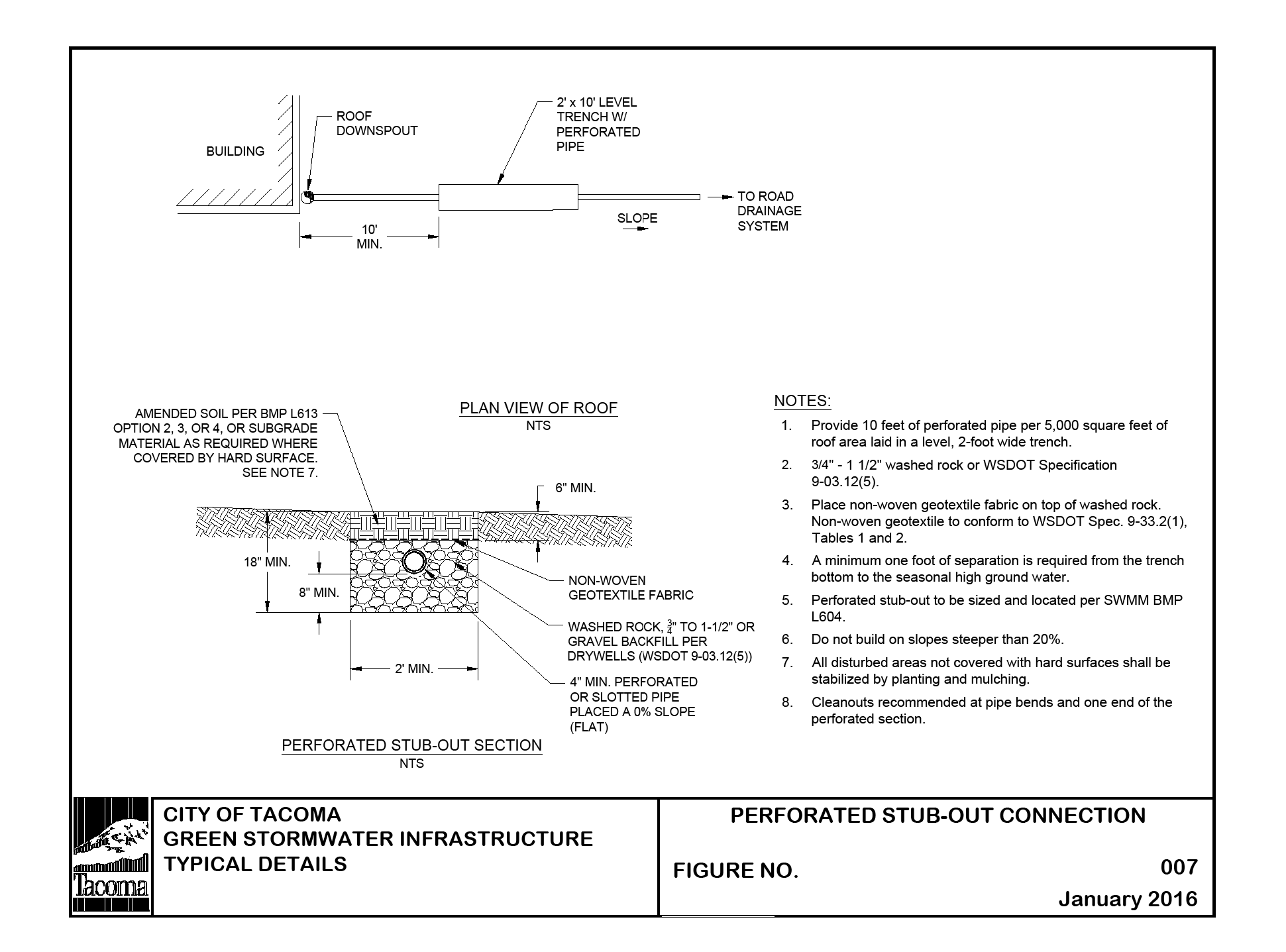
Perforated stub-out connections consist of at least 10 feet of perforated pipe per 5,000 square feet of roof area laid in a level, 2-foot wide trench backfilled with washed drain rock. Extend the drain rock to a depth of at least 8 inches below the bottom of the pipe and cover the pipe. Lay the pipe level and cover the rock trench with filter fabric and 6 inches of amended soil. (see Figure 4 - 9: Perforated Stub-Out Connections).
Select the location of the connection to allow a maximum amount of runoff to infiltrate into the ground (ideally a dry, relatively well drained, location).
To facilitate maintenance, do not locate the perforated pipe portion of the system under impervious or heavily compacted (e.g., driveways and parking areas) surfaces.
Perforated stub-outs may be placed in fill material if the fill is placed and compacted under the direct supervision of a Washington State Licensed Professional Engineer, and if the measured infiltration rate of the fill material is at least 8 inches per hour. Infiltration rate must be determined using methods in Appendix A - Appendix A Determining the Design Infiltration Rate.
Non-woven geotextile fabric shall be placed over the trench aggregate prior to backfilling. The non-woven geotextile shall conform to A2000 - Geotextile Specifications, Geotextile for Underground Drainage - Low Survivability, Class C.
Distribution pipe shall be minimum 4” PVC slotted or perforated pipe placed at 0% slope.
Rock layer shall be ¾” to 1½” washed rock or rock meeting WSDOT Standard Specification 9-03.12(5) - Gravel Backfill for Drywells. A minimum 12” layer of rock shall be placed under the perforated or slotted pipe.
8.3.6 Perforated Stub-Out Modeling
Flow credits are not applicable to perforated stub-out connections. Any flow reduction is variable and unpredictable. No computer modeling techniques are allowed that would predict any reduction in flow rates and volumes from the connected area.
Figure 4 - 9: Perforated Stub-Out Connections
