13.1 BMP T1010 - Basic Biofiltration Swale
Basic biofiltration swales are vegetation-lined channels designed to remove suspended solids from stormwater. The shallow, concentrated flow allows for filtration of stormwater by the vegetation.
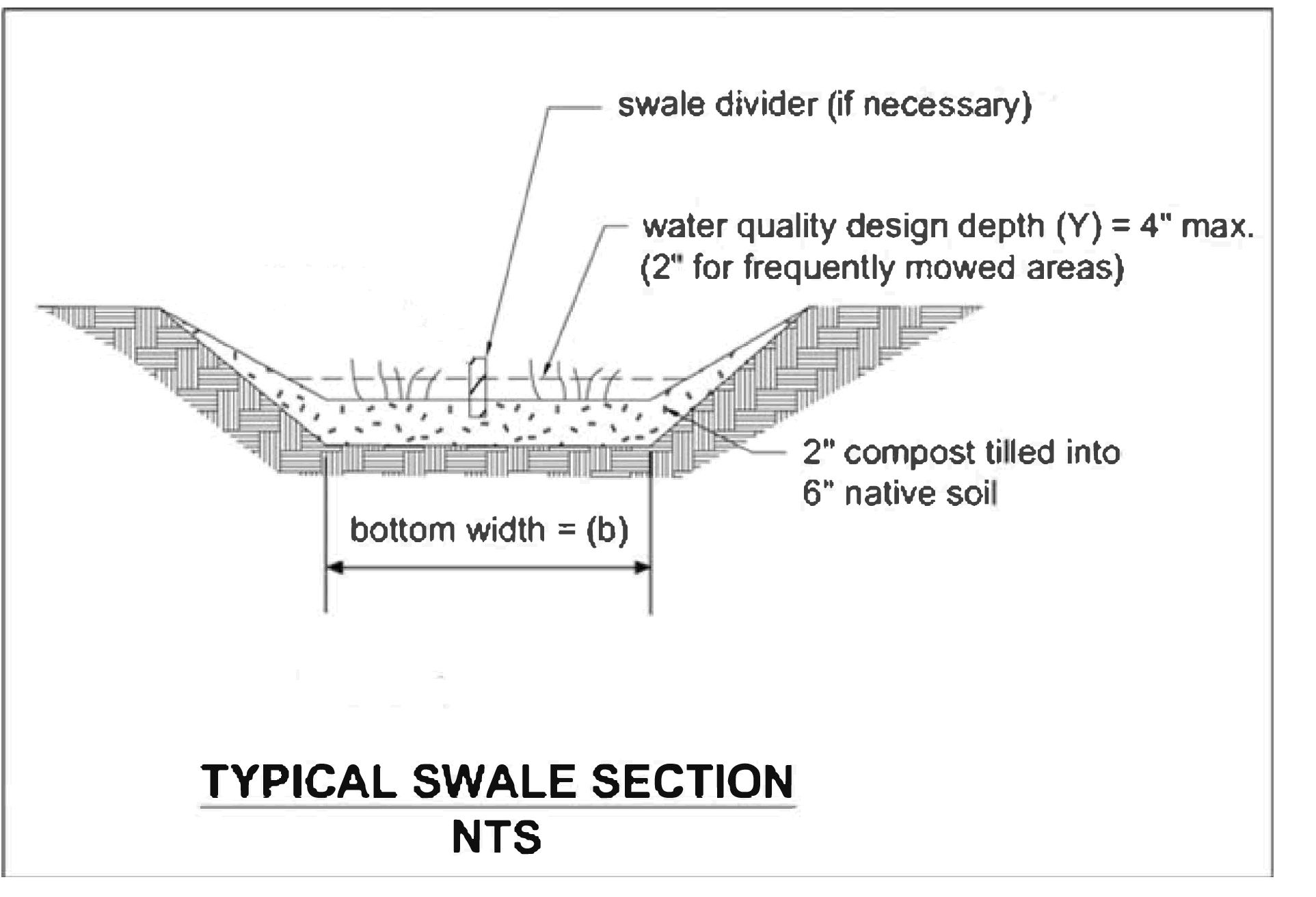
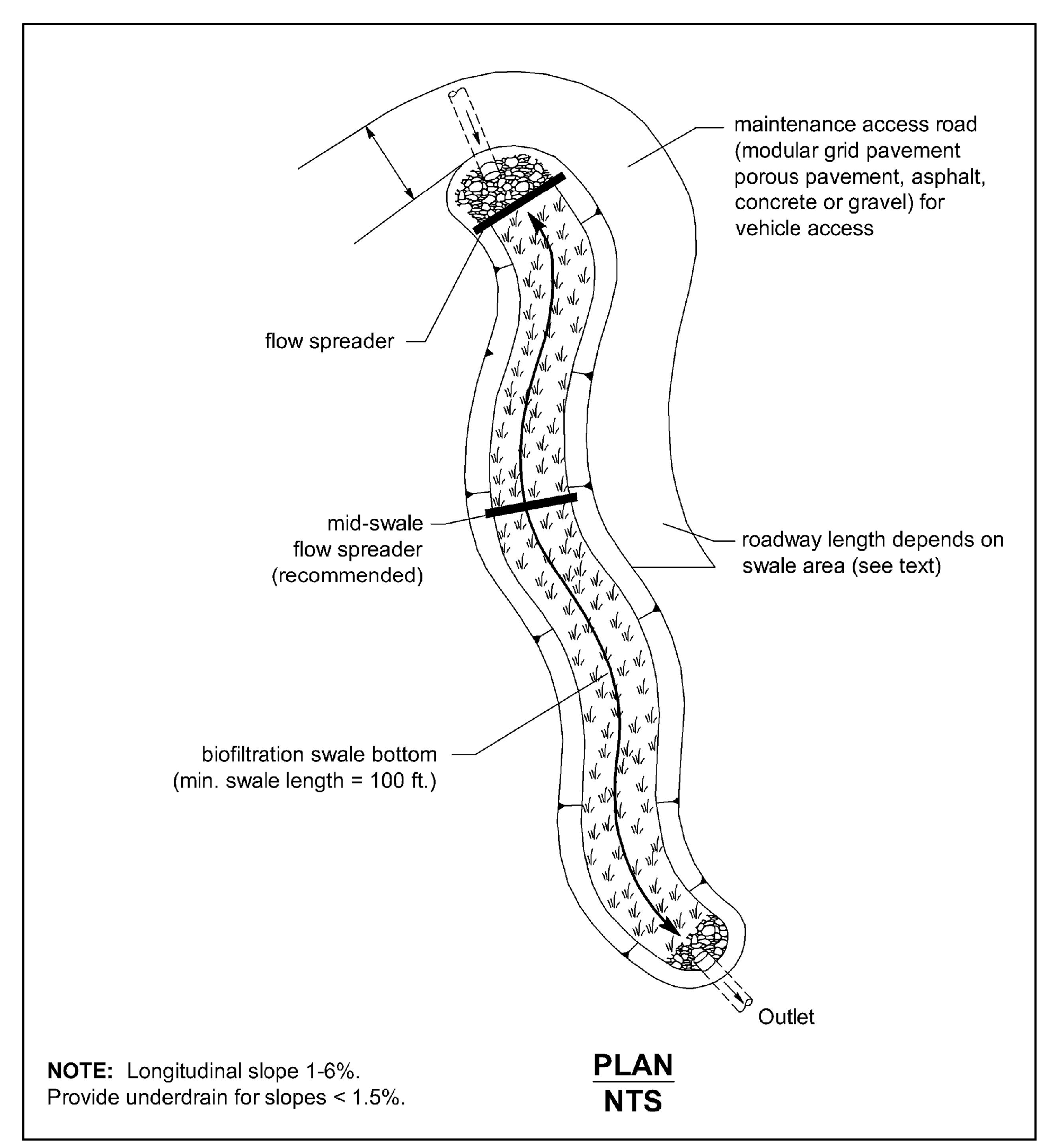
Figure 4 - 14: Typical Swale Section
13.1.2 Applications and Limitations
Basic biofiltration swales can be used to help ensure compliance with Minimum Requirement 6 - Stormwater Treatment.
The performance of biofiltration swales is variable between storm events and is therefore not a consistent treatment BMP.
Comply with all criteria and standards in Modeling Your Best Management Practices, Design Criteria for All Stormwater Treatment and Flow Control BMPs, Constructing Your Best Management Practices and Accessing and Maintaining Your Best Management Practices as applicable to the project in addition to criteria within each BMP. Where criteria or standards conflict, utilize the criteria and standards contained within the specific BMP.
Basic biofiltration swales may be located upstream or downstream of detention facilities. If placed downstream from detention, prolonged flows may reduce grass survival and a wet biofiltration swale or other BMP may be more appropriate.
Basic biofiltration swales shall be designed using the design criteria in Table 4 - 14: Design Criteria for Basic Biofiltration Swale and design criteria within this section.
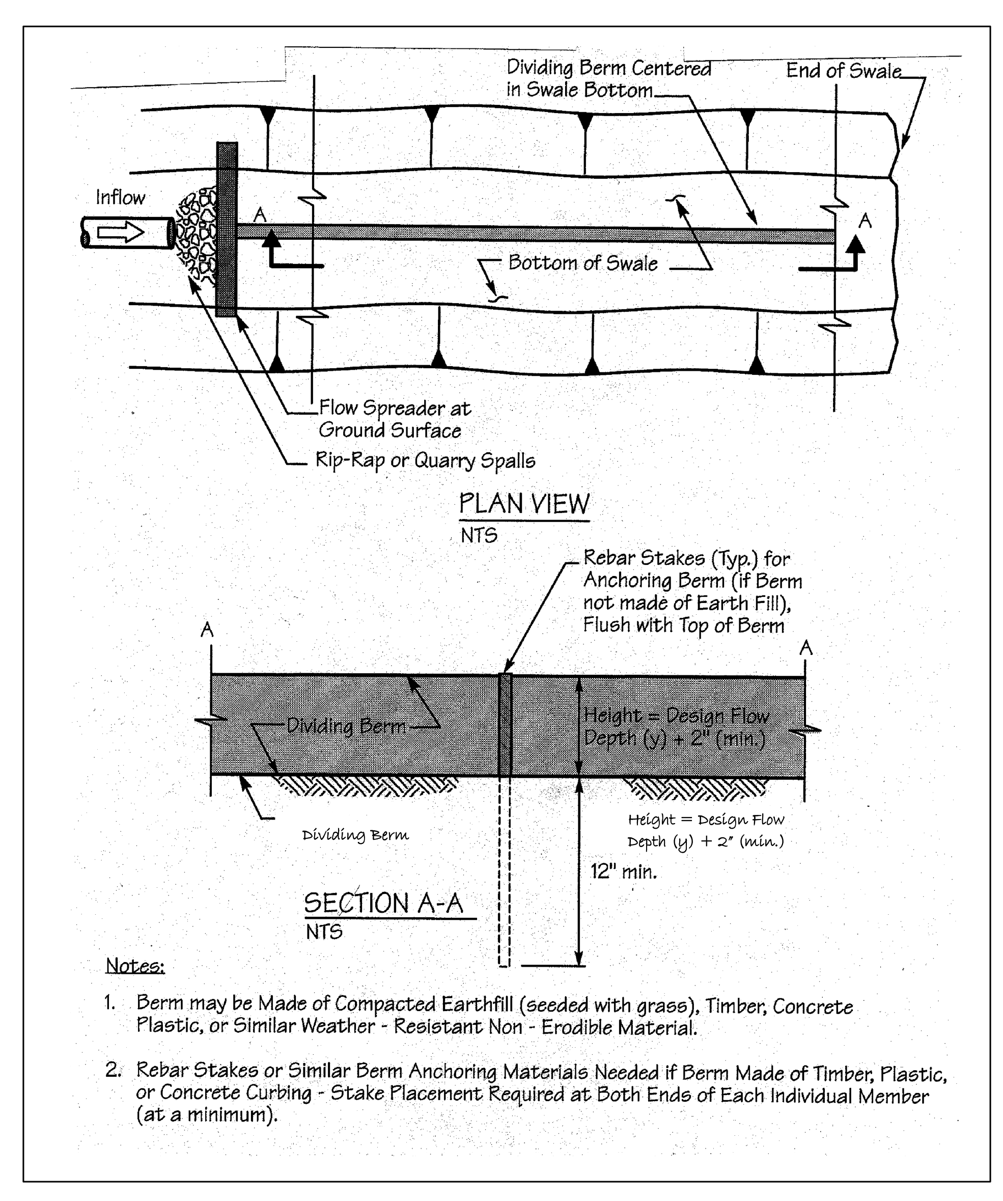
Table 4 - 14: Design Criteria for Basic Biofiltration Swale 2 - 10 ft (swale widths up to 16 feet may allowed with a swale dividing berm per Figure 4 - 16: Swale Dividing Berm).
13.1.4 Sizing Procedure for Biofiltration Swales
Project proponents may utilize the biofiltration swale spreadsheet available at www.cityoftacoma.org/stormwatermanual to calculate the appropriate biofiltration size for a project. The spreadsheet uses the procedure below.
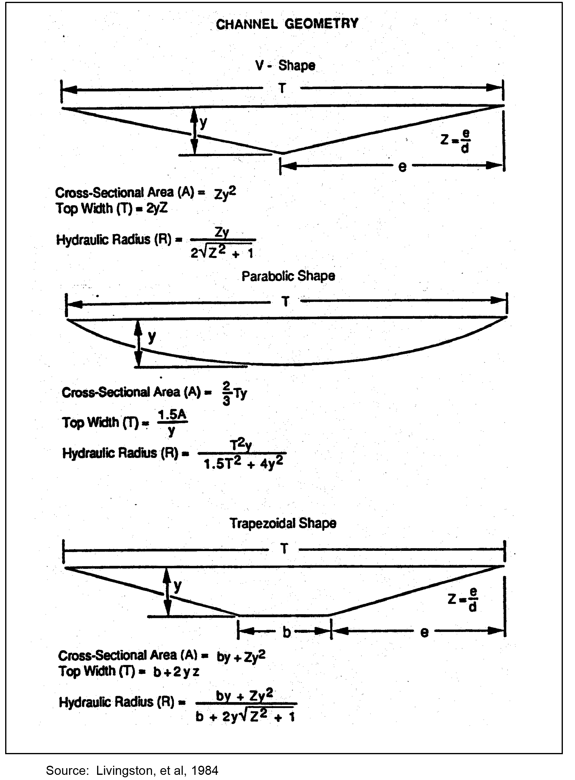
These calculations below assume the biofiltration swale will be constructed as a trapezoid. If an alternate biofiltration swale shape is proposed, alter the equations for the proposed shape as necessary. See Figure 4 - 15: Geometric Formulas for Common Swale Shapes.
Determine the water quality design flowrate (Qwq) using an Ecology approved continuous simulation model, assuming a 15-minute timestep.
Determine the biofiltration design flowrate (Qbiofil) using the equation below.
Establish the longitudinal slope of the proposed biofiltration swale. Longitudinal slope shall be between 0.015-0.025 feet per foot.
Select the type of vegetation and depth of flow (based on frequency of mowing and type of vegetation).
Select a value of Manning’s n (see Table 4 - 14: Design Criteria for Basic Biofiltration Swale based on vegetation type and frequency of mowing)
Use Manning’s equation and first approximations relating hydraulic radius and dimensions for the selected swale shape to obtain a working value of a biofiltration swale bottom and top width dimension:
Qbiofil = Biofiltration design flowrate, calculated in D2.
n = Manning's n (dimensionless)
s = Longitudinal slope as a ratio of vertical rise/horizontal run (dimensionless)
A = cross-sectional area (ft2)
R = hydraulic radius (ft)
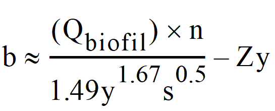
Because the depth of flow in most biofiltration swales is shallow relative to the bottom width, channel side slopes can be ignored in the calculation of bottom width. Use the following equation to estimate the swale bottom width for a trapezoidal swale.
Qbiofil = Biofiltration design flowrate calculated in D2.
Z = Side slope (for trapezoid select 3)
A minimum 2-foot bottom width is required. If the calculated bottom width is less than 2 feet, use 2 for design for the remainder of the equations.
Atrapezoid = cross-sectional area (ft²)
b = bottom width of trapezoid (ft)
Compute the flow velocity (Vbiofil) at Qbiofil:
A = cross-sectional area (ft2)
Qbiofill = Biofiltration design flowrate, calculated in D.2.
If V >1.0 ft/sec , alter design and repeat calculations until the condition is met. A velocity greater than 1.0 ft/sec was found to flatten grasses, thus reducing filtration. A velocity lower than this maximum value will allow a 9-minute hydraulic residence time criterion in a shorter biofilter.
t = hydraulic residence time (min). See Table 4 - 14: Design Criteria for Basic Biofiltration Swale.
Vbiofil = velocity at Qbiofil (ft/sec)
Qbiolfil = biofiltration design flowrate as calculated in D.2.
If a biofilter length is greater than the space permits, follow the advice in D.10.
If a length less than 100 feet results from this analysis, increase it to 100 feet, the minimum allowed. In this case, it may be possible to save some space in width and still meet all criteria. This possibility can be checked by computing V in the 100 ft biofiltration swale for t = 9 minutes, recalculating A (if V < 1.0 ft/sec) and recalculating T.
If there are space constraints, the local government and the project proponent should consider the following solutions (listed in order of preference):
Divide the contributing area into multiple biofiltration swales.
Use infiltration or other low impact development techniques to provide lower discharge rates to the biofiltration swale (only if the Site Suitability Criteria are met).
Increase vegetation height and design depth of flow (note: the design must ensure that vegetation remains standing during design flow).
Reduce the developed surface area to gain space for biofiltration.
Increase the longitudinal slope.
Nest the biofiltration swales within or around another BMP.
Note the Final Calculated Biofiltration Swale Dimensions.
Calculate the total final swale depth (yswale)
y was chosen in D.4.
Complete the Freeboard Check to Obtain the Total Required Swale Depth.
The freeboard check must be performed for the combination of highest expected flow and least vegetation coverage and height. A check is not required for biofiltration swales that are located offline from the primary conveyance/detention system. Maintain the same units as in the biofiltration capacity analysis.
The maximum permissible velocity for erosion prevention (Vmax) is 3 feet per second.
Determine Qconvey which is the 100-year, return frequency flow using an Ecology approved continuous simulation model and assuming a 15-minute timestep.
Calculate the flow depth at Qconvey
Qconvey = 100-year, return frequency flow from F.1.
s = longitudinal slope as determined from Design Steps
b = biofiltration swale width as calculated from Design Steps
Calculate total required swale depth (yswale)
Review all of the criteria and guidelines for biofilter planning, design, installation, and operation above and specify all of the appropriate features for the application.
Figure 4 - 15: Geometric Formulas for Common Swale Shapes
Figure 4 - 16: Swale Dividing Berm
13.1.5 Level Spreaders and Energy Dissipators
Construct level spreaders and swale dividers of plastic boards, concrete, or other materials that will not leach contaminants. Stake level spreaders with nongalvanized metal pins at 4 feet on center minimum.
Install level spreaders at the head of all swales, and every 50 feet in swales greater than or equal to 4 feet width. Install level spreaders at the head of the biofiltration swale if a swale divider is used. Include sediment cleanouts (weir, settling basin, or equivalent) at the head of the biofiltration swale as needed
Use energy dissipaters (such as check dams) for swales on longitudinal slopes exceeding 2.5%. Energy dissipaters may take the place of level spreaders if they are designed and installed to maintain level flow in the swale.
Use the following list as a guide for choosing appropriate soils for the biofiltration swale.
Composted organic matter 10-30 % (excluding animal waste, toxics)
Compost shall comply with A900 - Compost.
Use compost amended soil where practicable.
Till to at least 8-inch depth.
For longitudinal slopes of < 2 percent use more sand to obtain more infiltration.
If groundwater contamination is a concern, seal the bed with clay or a geomembrane liner - see A100 - Liners.
See A1000 - Vegetation for recommended grasses, wetland plants, and groundcovers.
Select fine, turf-forming, water-resistant grasses where vegetative growth and moisture will be adequate for growth.
Irrigate if moisture is insufficient during dry weather season.
Use sod with low clay content and where needed to initiate adequate vegetative growth. Preferably sod should be laid to a minimum of one-foot vertical depth above the swale bottom.
Consider sun/shade conditions for adequate vegetative growth and avoid prolonged shading of any portion not planted with shade tolerant vegetation.
Stabilize soil areas upslope of the biofilter to prevent erosion.
Fertilizing a biofilter shall not be allowed.
Do not put swale into operation until exposed soil in contributing area is stabilized.
Keep erosion and sediment control measures in place until swale vegetation is established.
Avoid compaction during construction.
Grade biofiltration swales to ensure longitudinal and lateral slopes are uniform.
Below the design water depth install an erosion control blanket, at least 4" of topsoil, and the selected biofiltration seed mix. Provide vegetation above the water line.
