13.4 BMP T1040 - Vegetated Filter Strip
A vegetated filter strip is flat with no side slopes (Figure 4 - 18: Typical Filter Strip). Untreated stormwater is distributed as sheet flow across the inlet width of a biofilter strip.
13.4.2 Applications/Limitations
The vegetated filter strip is typically used online and adjacent and parallel to a paved area such as parking lots, driveways, and roadways.
13.4.3 Design Criteria for Vegetated Filter strips
Comply with all criteria and standards in Modeling Your Best Management Practices, Design Criteria for All Stormwater Treatment and Flow Control BMPs, Constructing Your Best Management Practices and Accessing and Maintaining Your Best Management Practices as applicable to the project in addition to criteria within each BMP. Where criteria or standards conflict, utilize the criteria and standards contained within the specific BMP.
Vegetated filter strips shall not be located downstream of detention facilities.
Use the Design Criteria specified in Table 4 - 17: Design Criteria for Vegetated Filter Strips.
Filter strips shall only receive sheet flow.
Use curb cuts ≥ 12-inch wide and 1-inch above the filter strip inlet
. Table 4 - 17: Design Criteria for Vegetated Filter Strips Sufficient to achieve hydraulic residence time in the filter strip 0.05 (steeper than 0.05 need upslope flow spreading and energy dissipation)
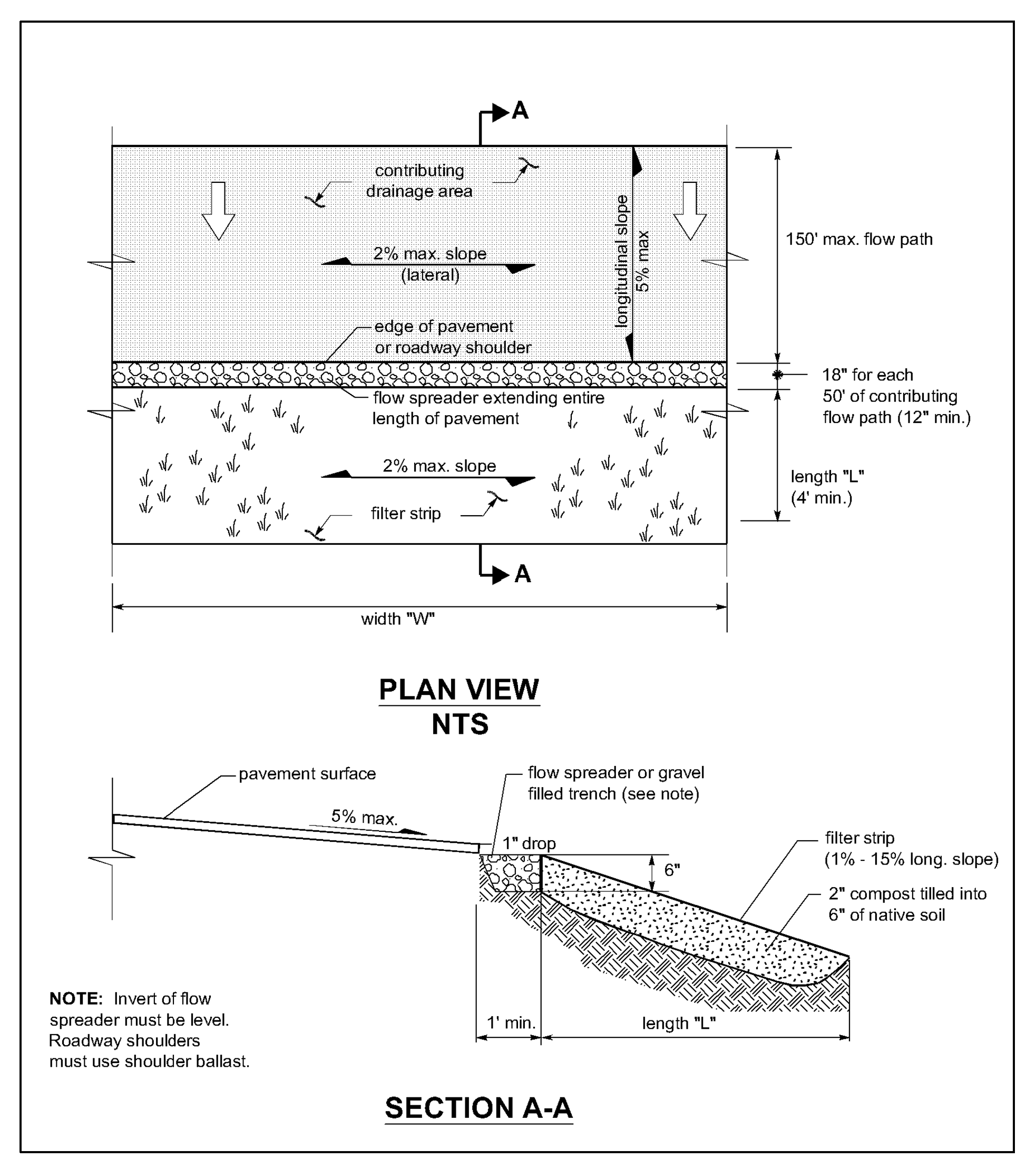
Figure 4 - 18: Typical Filter Strip
13.4.4 Sizing Procedure for Vegetated Filter Strips
Use the design parameters in Table 4 - 17: Design Criteria for Vegetated Filter Strips above in the equations below as applicable.
Project proponents may utilize the Vegetated Filter Strip spreadsheet available at www.cityoftacoma.org/stormwatermanual to calculate the appropriate vegetated filter strip size for a project. The spreadsheet uses the procedure below.
Determine the water quality design flowrate (Qwq) using an Ecology approved continuous simulation model, assuming a 15-minute timestep.
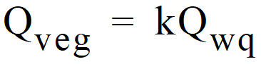
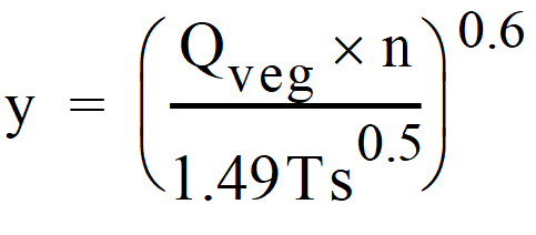
Determine the vegetated filter strip design flowrate (Qveg) using the equation below.
Calculate the design flow depth using Manning’s equation as follows:
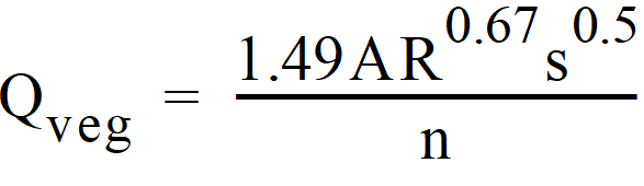
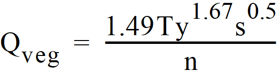
y = Rrectangle, design depth of flow, ft. (1 inch maximum)
n = Manning’s roughness coefficient = 0.35
s = Longitudinal slope of filter strip parallel to direction of flow, feet per foot
T = Width of filter strip perpendicular to the direction of flow, ft.
A = Filter strip inlet cross-sectional flow area (rectangular), ft2
Calculate the design flow velocity V, ft./sec., through the vegetated filter strip:
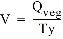
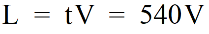
Calculate required length, ft., of the filter strip at the minimum hydraulic residence time, t, of 9 minutes: