8.2 BMP L603 - Downspout Dispersion
Downspout dispersion systems are splash blocks or dispersion facilities that spread roof runoff over vegetated pervious areas. Dispersion attenuates peak flows by slowing stormwater.
This BMP can be utilized to ensure compliance with Minimum Requirement 5 - Onsite Stormwater Management.
The BMP can be used solely to mitigate for roof surfaces if utilizing the List Approach or may be used in combination with other BMPs to satisfy the LID Performance Standard.
This BMP may also be used to help ensure compliance with Minimum Requirement 7 - Flow Control and Minimum Requirement 8 - Wetlands Protection.
Where compliance with Minimum Requirements is not required, where feasible, this BMP is recommended to be used to help protect receiving waterbodies from the effects of stormwater.
8.2.3 Infeasibility Criteria for Roof Downspout Dispersion
The following infeasibility criteria describe conditions that make downspout dispersion infeasible when applying The List Approach for compliance with Minimum Requirement 5 - Onsite Stormwater Management.
The infeasibility criteria shall also be used to determine the appropriateness of installing downspout dispersion on a project site. Project proponents may be allowed to install downspout dispersion even if considered infeasible provided documentation is included that substantiates the design. Documentation may be required by a Washington State Licensed Professional Engineer or other appropriate professional depending on the project conditions.
A site characterization study must be completed in order to determine if the infeasibility criteria apply and to determine the appropriateness of installing downspout dispersion systems.
The design standards per BMP L603a - Downspout Dispersion Trenches or BMP L603b - Splashblocks cannot be met.
The setback criteria below cannot be met. Setback criteria are generally required by the Tacoma Municipal Code, Uniform Building Code requirements, the Tacoma Pierce County Health Department, or other state regulations. Where a conflict between setbacks occurs, the City shall require compliance with the most stringent of the setback requirements from various codes/regulations. The following are the minimum setbacks required per this manual.
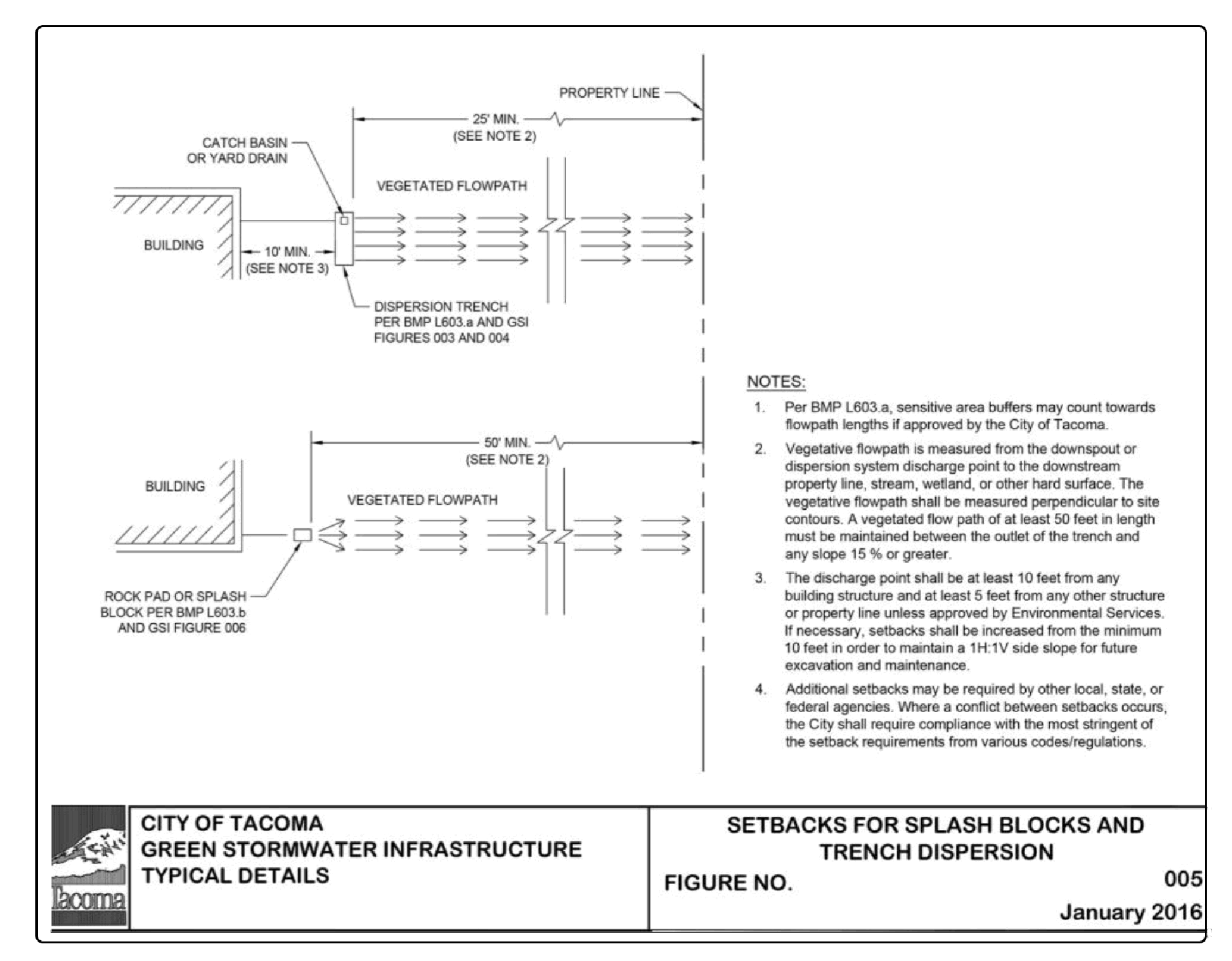
At least 10 feet from any building and at least 5 feet from any property line or structure. If necessary, setbacks shall be increased from the minimum 5 feet in order to maintain a 1:1 side slope for future excavation and maintenance.
A minimum of 50 feet from the top of any slope greater than 15% and from geologically hazardous areas. The dispersion system may be sited within 50 feet of a slope greater than 15% and/or geologically hazardous area if a geotechnical analysis performed by a Washington State Licensed Professional Engineer or Washington State Licensed Professional Geologist determines that there will be no negative impacts to the slopes and/or geologically hazardous areas caused by the dispersion system.
Figure 4 - 5: Setbacks for Splashblocks and Trench Dispersion (also Green Stormwater Infrastructure Figure 005) provides a detail showing setback requirements for dispersion BMPs.
If there are any conflicts with any of the following competing needs criteria:
Requirements of the following federal or state laws, rules, and standards:
Historic Preservation Laws and Archaeology Laws as listed at: https://dahp.wa.gov/project-review/preservation-laws
Federal Superfund or Washington State Model Toxics Control Act
Federal Aviation Administration requirements for airports
American with Disabilities Act
When found to be in conflict with special zoning district design criteria adopted and being implemented pursuant to a community planning process.
Public health and safety standards
Transportation regulations to maintain the option for future expansion or multi-modal use of public rights-of-way.
City of Tacoma Critical Area Ordinances that provides protection of tree species or other critical areas.
BMP L603a - Downspout Dispersion Trenches
The vegetated flowpath is less than 25 feet between the trench outlet and any property line, structure, stream, wetland, other infiltration or dispersion system, or impervious surface.
The vegetated flowpath is less than 50 feet between the trench outlet and any slope 15% or greater.
Sensitive area buffers may count towards flowpath lengths if approved by the City of Tacoma.
The vegetated flowpath is less than 50 feet between the discharge location and any property line, structure, slopes over 15%, stream, wetland, lake, other infiltration or dispersion system, or impervious surface.
Sensitive area buffers may count towards flowpath lengths if approved by the City of Tacoma.
The use of a splash block or dispersion trench would cause erosion or flooding problems onsite or on adjacent properties. Citation of this infeasibility criterion requires evaluation of site specific conditions and a stamped and signed memo or report from a Washington State Licensed Professional Engineer.
8.2.4 General Design Criteria for Downspout Dispersion
Comply with all criteria and standards in Modeling Your Best Management Practices, Design Criteria for All Stormwater Treatment and Flow Control BMPs, Constructing Your Best Management Practices and Accessing and Maintaining Your Best Management Practices as applicable to the project in addition to criteria within each BMP. Where criteria or standards conflict, utilize the criteria and standards contained within the specific BMP.
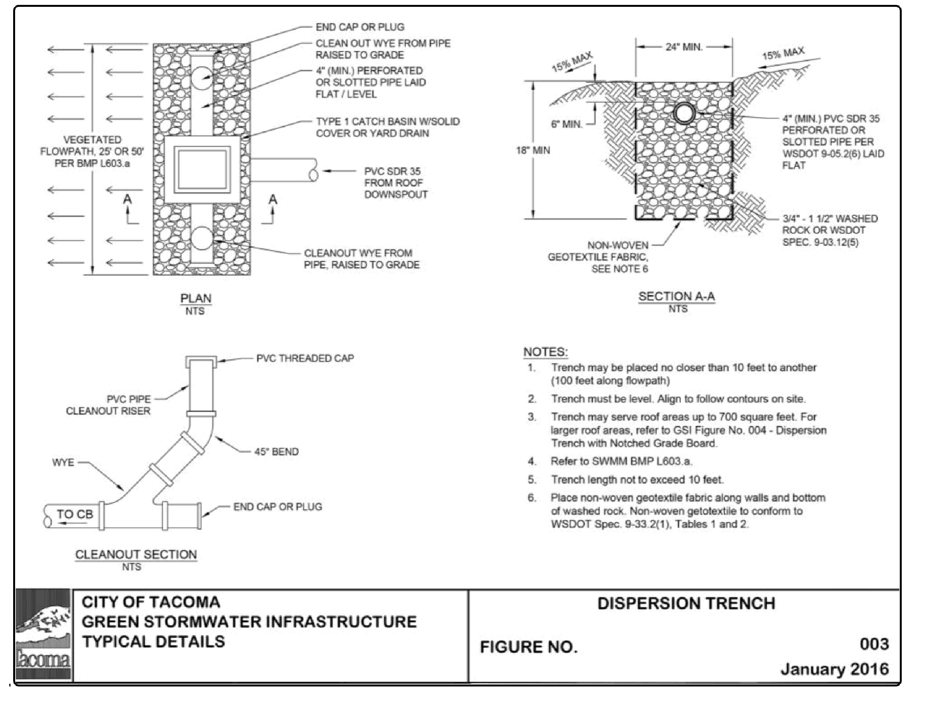
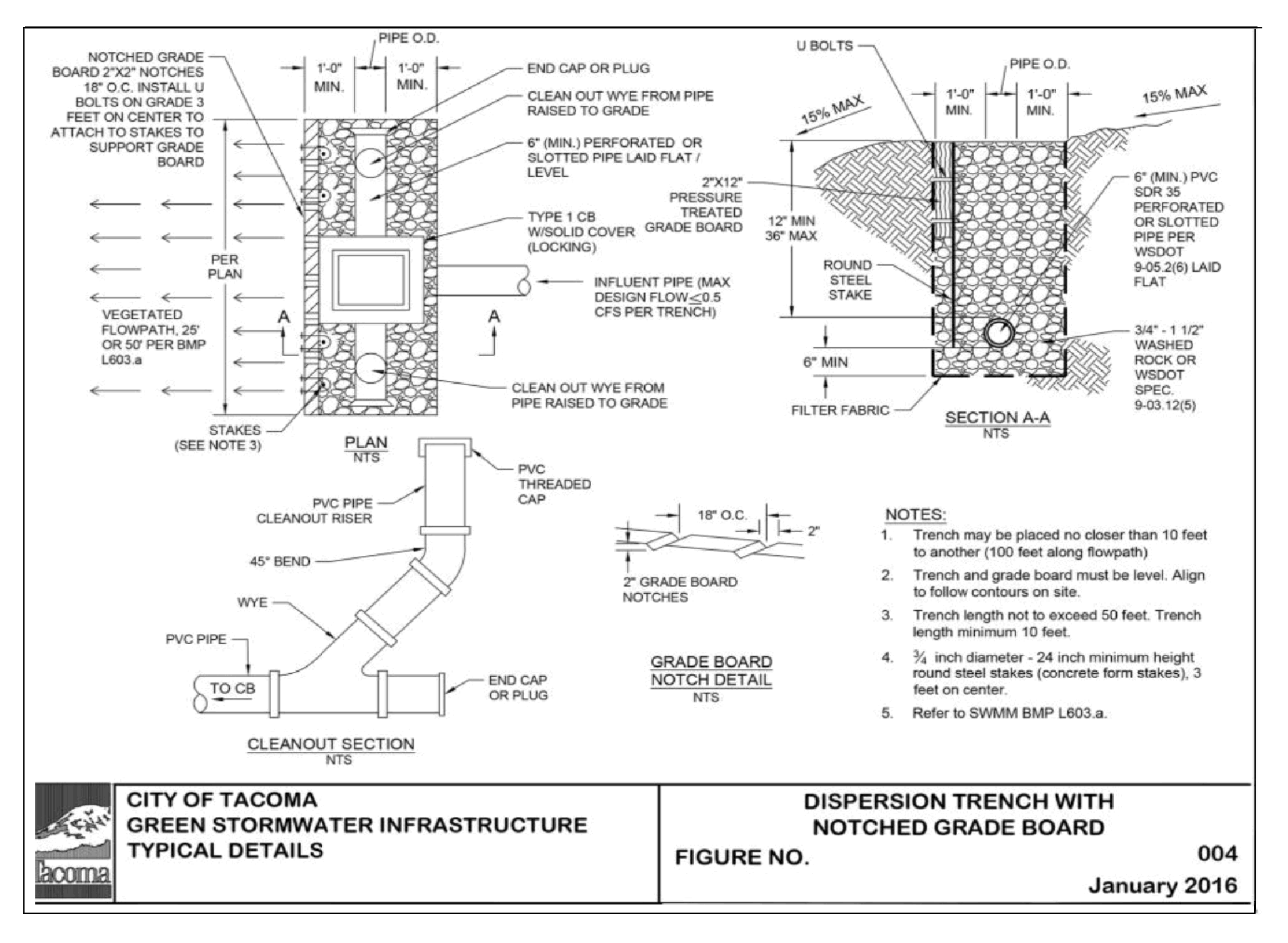
Downspout dispersion trenches designed as shown in Figure 4 - 6: Downspout Dispersion Trench or (also called Green Stormwater Infrastructure Figure 003 and Figure 004 shall be used for all downspout dispersion applications except where splash blocks are allowed.
The vegetated flowpath must consist of well-established lawn or pasture, landscaping with well-established vegetative groundcover, native vegetation with natural groundcover, or an area that has been amended to meet BMP L613 - Post-Construction Soil Quality and Depth and Depth. Groundcover must be dense enough to disperse stormwater and prevent erosion. Vegetation shall be established before the system is put online to avoid erosion.
Install a catch basin or yard drain where the roof downspout system pipe connects to the dispersion trench.
Catch basin or yard drain shall have a minimum 6" sump depth below the tee.
Setbacks from Onsite Sewage Systems shall conform to WAC 246-272A-0210.
For sites with multiple dispersion systems, the outer edge of the vegetated flowpath segment for the dispersion trench must not overlap with other flowpath segments, except those associated with sheet flow from a native or non-native pervious surface.
Dispersion system shall be setback a minimum of 50 feet from the top of any slope greater than 15% and from geologically hazardous areas. The dispersion system may be sited within 50 feet of a slope greater than 15% and/or geologically hazardous area if a geotechnical analysis performed by a Washington State Licensed Professional Engineer or Washington State Licensed Professional Geologist determines that there will be no negative impacts to the slopes and/or geologically hazardous areas caused by the dispersion system.
8.2.5 BMP L603a - Design Criteria for Downspout Dispersion Trenches
Design downspout dispersion trenches as shown in Figure 4 - 6: Downspout Dispersion Trench or (also called Green Stormwater Infrastructure Figure 003 and Figure 004 available at https://www.cityoftacoma.org/government/city_departments/public_works/engineering/standard_plans_and_g_i_s_typical_details).
A vegetated flowpath of at least 25 feet in length must be maintained between the outlet of the trench and any property line, structure, stream, wetland, or impervious surface. A vegetated flowpath of at least 50 feet in length must be maintained between the outlet of the trench and any slope, 15% or greater. Sensitive area buffers may count towards flowpath lengths if approved by the City of Tacoma.
Trenches serving up to 700 square feet of roof area may be simple 10-foot-long by 2-foot wide washed rock filled trenches as shown in Figure 4 - 6: Downspout Dispersion Trench. For roof areas larger than 700 square feet, a dispersion trench with notched grade board may be used as approved by the City. The total length of this design must not exceed 50 feet and must provide at least 10 feet of trench per 700 square feet of roof area.
Trenches shall not be placed closer than 10 feet from edge of trench to edge of trench or be placed closer than 100 feet along the flowpath.
Distribution pipe shall be minimum 4” PVC slotted or perforated pipe placed at 0% slope.
Rock layer material shall be ¾” to 1½” washed rock or rock meeting WSDOT Standard Specification 9-03.12(5) Gravel Backfill for Drywells. A minimum 12” layer of rock shall be placed under the perforated or slotted pipe. Wrap rock layer in a non-woven geotextile fabric. The non-woven geotextile shall conform to A2000 - Geotextile Specifications, Geotextile for Underground Drainage - Low Survivability, Class C.
Cleanout are recommended at all bends in pipe and at the trench terminus for inspection and maintenance practices.
Catch basin or yard drain shall have a minimum 6” sump depth below tee invert elevation.
8.2.6 BMP L603b - Design Criteria for Splashblocks
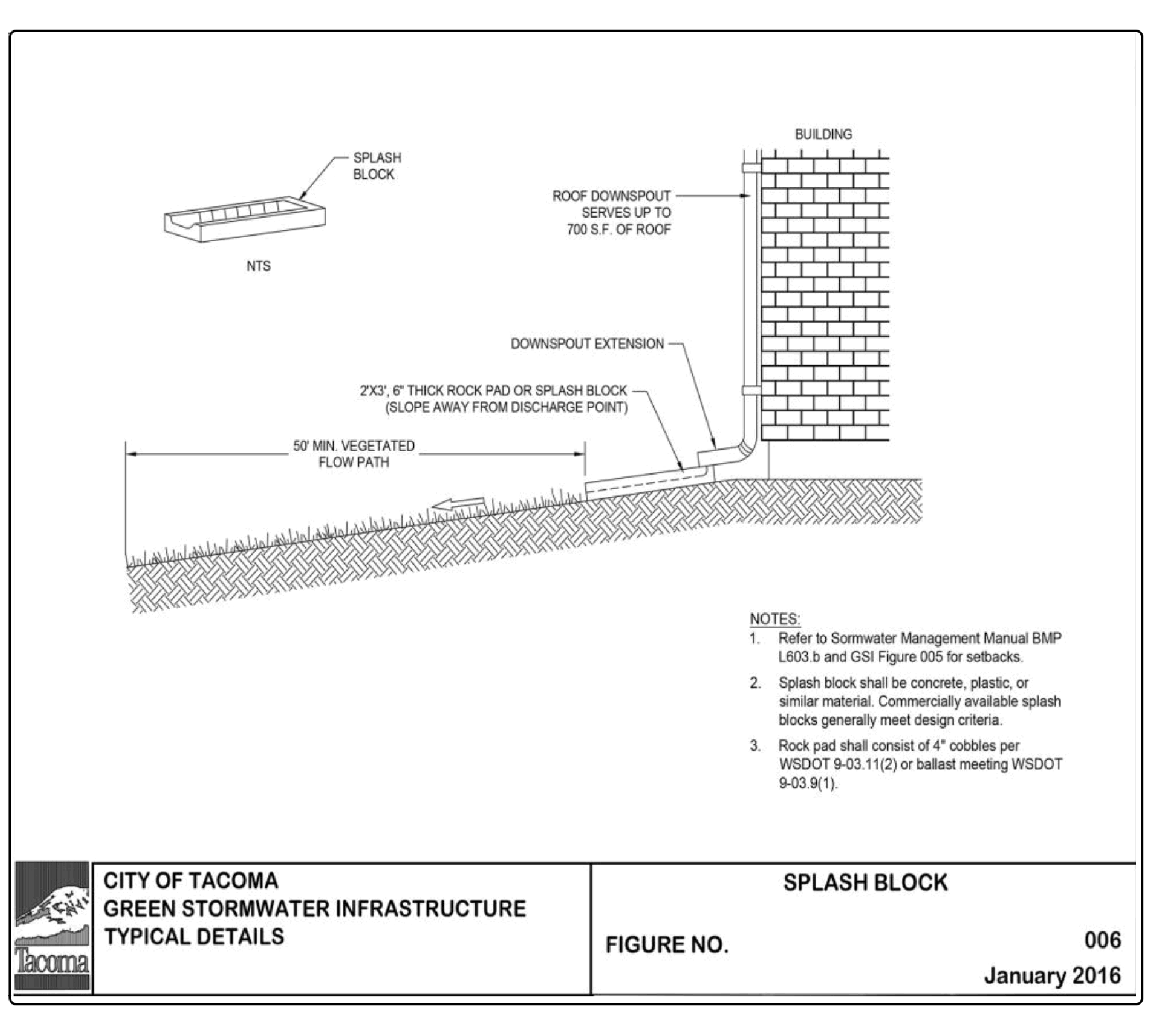
Design splashblocks as shown in Figure 4 - 8: Downspout Splashblock Dispersion (also known as Green Stormwater Infrastructure Figure 006 - available at https://www.cityoftacoma.org/government/city_departments/public_works/engineering standard_plans_and_g_i_s_typical_ details). In general, if the ground is sloped away from the foundation and there is adequate vegetation and area for effective dispersion, splashblocks will adequately disperse runoff. If the ground is fairly level, if the structure includes a basement, or if footing drains are proposed, splashblocks with downspout extensions may be a better choice because the discharge location is moved away from the footing. Downspout extensions can include piping to a splashblock/discharge location a considerable distance from the downspout, as long as the runoff can travel through a well-vegetated area as described below.
A vegetated flowpath of at least 50 feet shall be maintained between the discharge location and any property line, structure, slopes over 15%, stream, wetland, lake, or other impervious surface. Sensitive area buffers may count toward flowpath lengths.
Flows shall not be directed onto sidewalks.
A maximum of 700 square feet of roof area may discharge to each splashblock.
A splashblock or a pad of cobbles or ballast (2 feet wide by 3 feet long by 6 inches deep) shall be placed at each downspout discharge location. Cobbles shall conform to WSDOT Standard Specification 9-03.11(2) - Streambed Cobbles. Ballast shall conform to WSDOT Standard Specification 9-03.9(1) - Ballast.
8.2.7 Downspout Dispersion Modeling
Use one of the following options, based on the proposed project site design to model the system:
When downspout dispersion trenches or splashblocks are used per the design criteria, and the vegetated flowpath length is 50 feet or more:
Model the connected roof area as a lateral flow impervious area.
Where multiple dispersion areas will be used, it is permissible to model the roof areas as landscaped areas so the project schematic in the continuous simulation model is manageable.
When downspout dispersion trenches or are used per the design criteria, and the vegetated flowpath is 25-50 feet:
Model the connected roof area as a lateral flow impervious area.
Where multiple dispersion areas will be used, it is permissible to model the roof area as 50% landscaped and 50% impervious area so the project schematic in the continuous simulation model is manageable.
Figure 4 - 5: Setbacks for Splashblocks and Trench Dispersion
Figure 4 - 6: Downspout Dispersion Trench
Figure 4 - 7: Dispersion Trench with Notched Grade Board
Figure 4 - 8: Downspout Splashblock Dispersion


