18.5 BMP T1200a - API (Baffle Type) Separators
18.5.1 Design Criteria for API Separators
The design criteria below are in addition to design criteria provided in the previous section.
API separators shall be divided into three compartments: a forebay, an oil separation cell and an afterbay.
The forebay is designed primarily to trap and collect sediment, support plug flow conditions and reduce turbulence.
The oil separation cell traps and holds oil as it rises from the water column, and it serves as a secondary sediment collection area.
The afterbay provides a relatively oil-free cell before the outlet and provides a secondary oil separation area.
The length of the forebay shall be approximately 1/3 to 1/2 the length of the vault. In addition, the surface area of the forebay must be at least 20 square feet per 10,000 square feet of impervious area draining to the separator.
A removable flow spreading baffle is required.
Extend baffle from the surface to a depth of up to ½ the vault depth.
Baffle height to water depth ratio shall be 0.85.
A removable sediment retaining baffle is required.
Extend baffle from the vault floor.
Baffle shall be a minimum 24" from the vault floor.
Baffle height to water depth ratio shall be 0.15.
Locate the baffle 1' from the oil retaining baffle (on the inlet side)
A window wall baffle may be used provided the area of the window opening is at least 3 times greater than the area of the inflow pipe.
A removable oil retaining baffle is required.
Locate approximately the distance equal to ¼ the total vault length from the outlet wall, or a minimum of 8 feet, whichever is greater.
The minimum length provides for maintenance.
Extend baffle down to a depth of at least 50% of the design water depth.
Baffle height to water depth ratio shall be 0.85.
The configuration shall be designed to minimize turbulence and entrainment of sediment.
Baffles may be fixed rather than removable if additional entry ports and ladders are provided so that both sides of the baffle are accessible to maintenance crews.
API separator vaults shall have a minimum length-to-width ratio of 5:1.
The design water depth (D) shall be a minimum of 3 feet deep and a maximum of 8 feet deep unless approved by Environmental Services/Site Development Group per Joint Administrative Policy and Procedure Directive No. 2021-02-001.
API separator vaults shall have a design water depth-to-width ratio of between 0.3 and 0.5.
18.5.2 Sizing Criteria for API separators
18.5.2.1 Sizing Criteria for Contributing Areas Less than 2 Acres
The Washington State Department of Ecology modified the API Sizing Criteria for smaller drainage areas by using the design hydraulic horizontal velocity, Vh for the design Vh/Vt rather than using the API minimum of Vh/Vt=15. The API Sizing Criteria is applicable for drainage areas 2 acres or greater. Use the following steps for sizing and API Separator when the contributing area is less than 2 acres.
Step 1: Calculate the Water Quality Design Flowrate (Qwq)
Use an Ecology approved continuous simulation model, assuming 15-minute timesteps, to determine the 15-minute offline water quality flowrate.
Convert the calculated Water Quality Design Flowrate to ft3/min.
Step 2: Calculate the Adjusted Water Quality Design Flowrate (Qadj)
Step 3: Calculate Vt using Sizing - Stoke’s Law
Step 4: Select depth and width based upon allowed maximum water depths and allowed depth-to-width ratios.
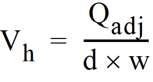
Step 5: Calculate the horizontal velocity of the bulk fluid (Vh).
Vh = Horizontal Velocity (ft/min)
Qadj calculated in Step 2. (ft3/min)
d = separator water depth (ft)
The maximum Vh allowed is 2 ft/min.
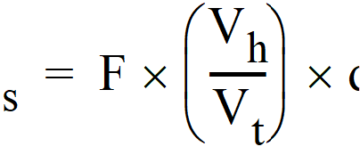
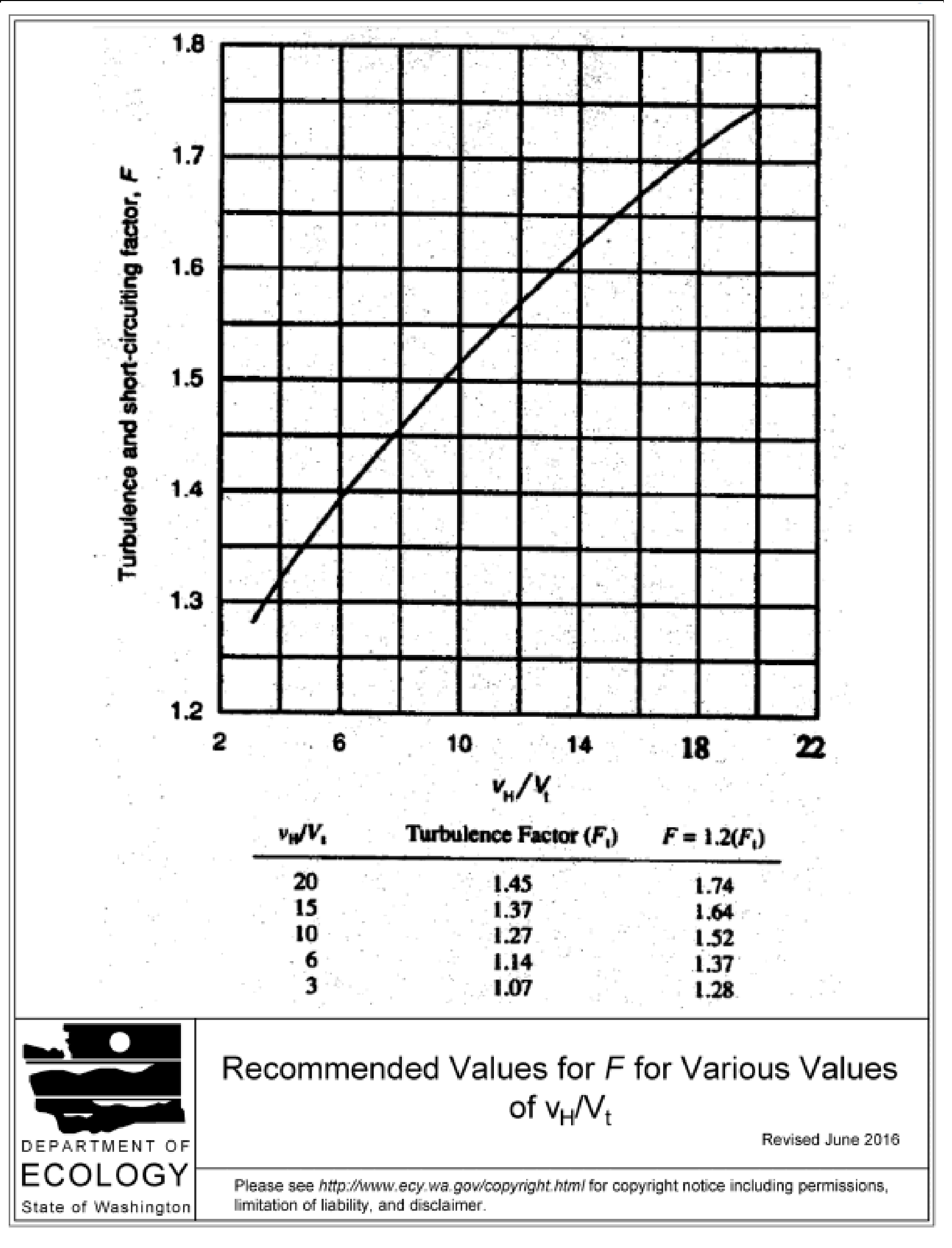
Step 7: Determine F - the turbulence and short-circuiting factor.
Use Figure 4-46 Turbulence and Short-Circuiting Factor to determine F.
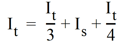
Step 8: Calculate the Minimum Separator Length Is.
It = total length of 3 bays (ft)
Step 9: Calculate the Minimum Hydraulic Design Volume (V)
V = minimum hydraulic design volume (ft3)
ls = separator Length as calculated in Step 8
w = width (ft) - chosen in Step 4
d = separator water depth (ft) - chosen in Step 4
Step 10: Calculate the Minimum Horizontal Area of the Separator Ah
Ah = minimum horizontal area of the separator (ft2)
ls = separator length - calculated in Step 8
w = width (ft) - chosen in Step 4
Step 11: Compute and Check that the Horizontal Surface Area of the Vault Forebay Criterion is Satisfied
This surface area of the forebay must be at least 20 ft2 per 10,000 ft2 of impervious area draining to the separator.
The length of the forebay (L/3) may be increased to meet the criterion without having to increase the overall length of the vault.
Step 12: Design the flow splitter and high-flow bypass.
See A200 - Flow Splitters for design information.
18.5.2.2 Sizing Criteria for Contributing Areas 2 Acres and Greater
Use  and repeat Steps 7 to 12 above.
Figure 4 - 46: Turbulence and Short-Circuiting Factor


