20.3 BMP F120 - Detention Tanks
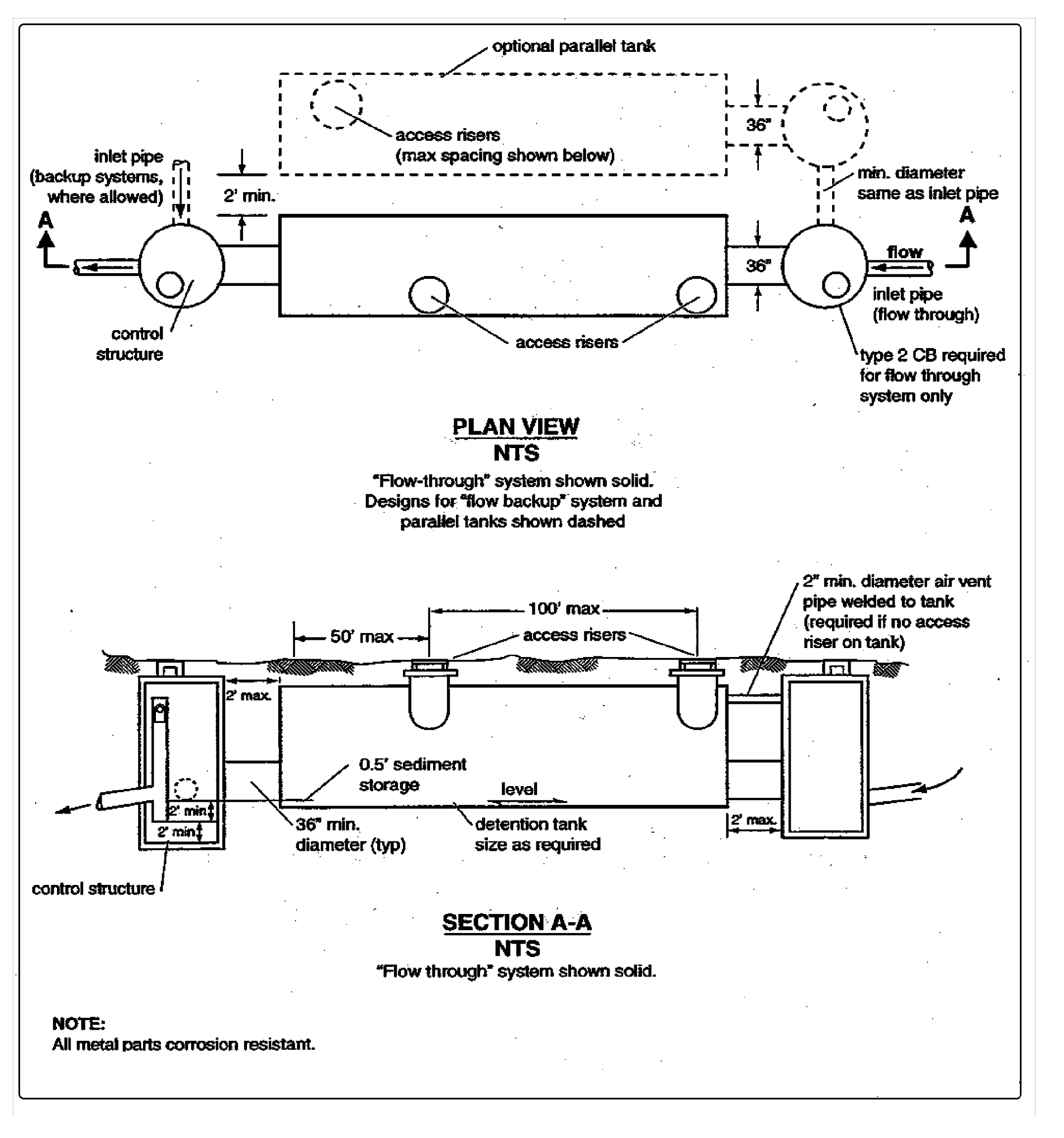
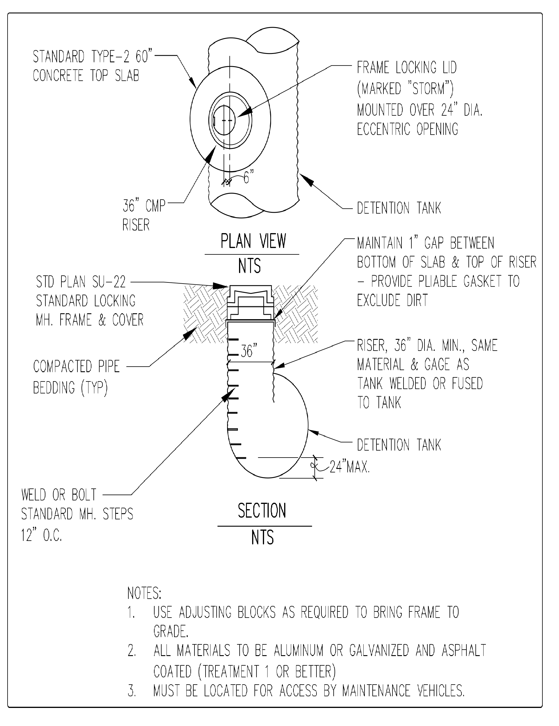
Detention tanks are underground storage facilities typically constructed using large diameter pipe. Standard detention tank details are shown in Figure 4 - 51: Typical Detention Tank and Figure 4 - 52: Detention Tank Access Detail. Control structure details are shown in A500 - Control Structures.
Certain of these requirements and design criteria shall also apply to other types of detention facilities, for example arch pipe detention facilities. Per Joint Administrative Policy and Procedure Directive No. 2021-02-001, Environmental Services/Site Development Group shall determine which requirements and design criteria are appropriate for various types of detention facilities.
Figure 4 - 51: Typical Detention Tank
Figure 4 - 52: Detention Tank Access Detail
Comply with Design Criteria for All Detention Facilities in addition to the design criteria below.
Tanks shall be designed as flow-through systems with manholes in line (see Figure 4 - 51: Typical Detention Tank) to promote sediment removal and facilitate maintenance. Detention facilities may be designed as back up systems if preceded by a Stormwater Treatment BMP.
The detention tank bottom shall be located 6 inches below the inlet and outlet to provide dead storage for sediment.
The minimum pipe diameter for a detention tank is 36 inches.
The minimum thickness for CMP shall be as follows:
16 gage for pipe diameters up to 84”
14 gage for pipe diameters 96” - 120”
12 gage for pipe diameters 126” - 138”
10 gage for pipe diameter 144”
Tanks with a diameter larger than 36 inches may be connected to each adjoining structure with a short section (2-foot maximum length) of 36-inch minimum diameter pipe. These sections shall not be considered as access when determining required access points.
Details of outflow control structures are given in A500 - Control Structures.
Parallel tanks shall be placed a minimum of two feet from each other measured from the edge of tank or pipe.
All tanks must meet structural requirements for overburden support and H20 traffic loading. Tanks located under roadways must meet City of Tacoma live load requirements.
Place tanks on stable, well consolidated native material with suitable bedding. Do not place tanks in fill slopes, unless analyzed by a Washington State Licensed Professional Engineer or Washington State Licensed Professional Geologist for stability.
The maximum depth from finished grade to tank invert shall be 20 feet.
Access openings shall be positioned a maximum of 50 feet from any location within the tank. A minimum of one access opening per tank shall be provided.
The maximum distance between access risers shall be 100 feet.
All tank access openings shall have round, solid locking lids (usually 1/2 to 5/8-inch diameter Allen-head cap screws).
Thirty-six inch minimum diameter riser-type manholes (see Figure 4 - 52: Detention Tank Access Detail) of the same gauge or thickness as the tank material may be used for access along the length of the tank and at the upstream terminus of the tank in a backup system. The top slab is separated (1-inch minimum gap) from the top of the riser to allow for deflections from vehicle loadings without damaging the riser tank.
All tank access openings must be readily accessible to maintenance vehicles.
Tanks must comply with the OSHA confined space requirements, which include clearly marking entrances to confined space areas. This may be accomplished by hanging a removable sign in the access riser(s) just under the access lid.

