15.1 BMP T1110 - Wetponds - Basic and Large
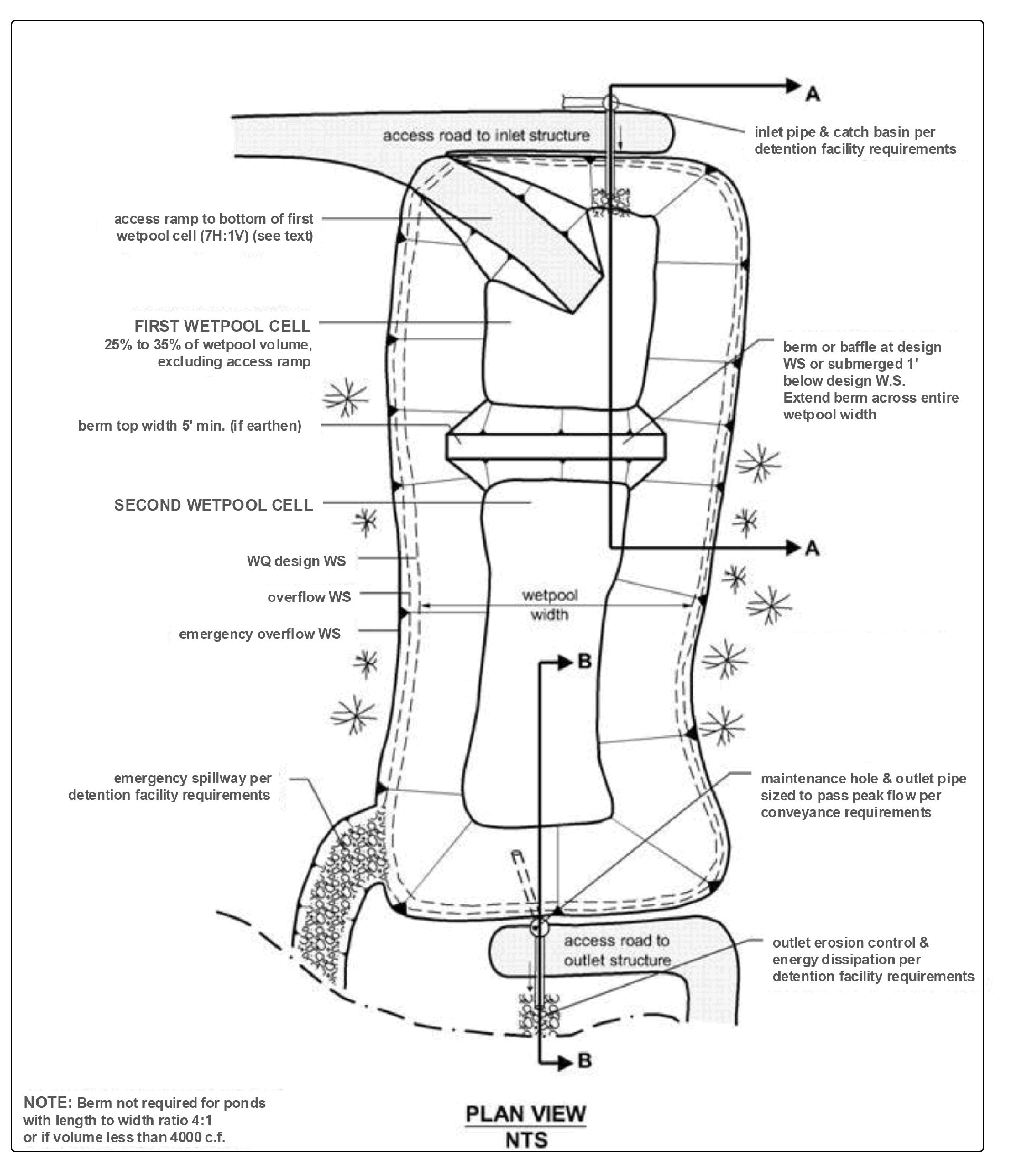
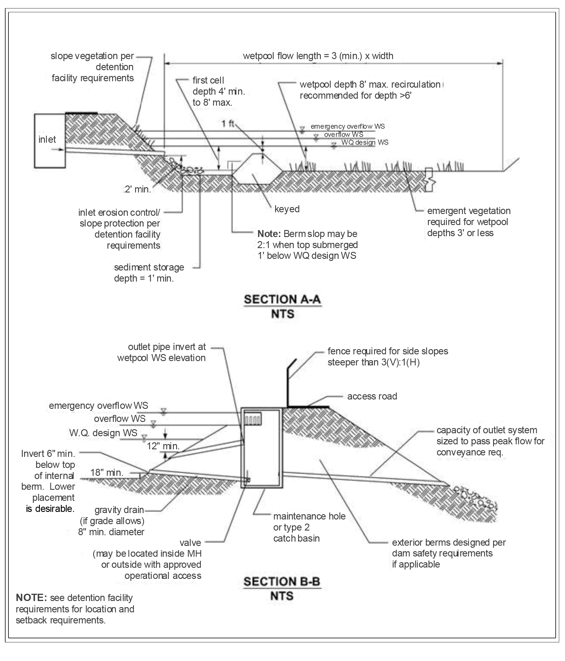
A wetpond is a constructed stormwater pond that retains a permanent pool of water ("wetpool") at least during the wet season. The volume of the wetpool is related to the effectiveness of the pond in settling particulate pollutants. As an option, a shallow marsh area can be created within the permanent pool volume to provide additional treatment for nutrient removal. Flow control can be provided in the "live storage" area above the permanent pool. Figure 4 - 36: Wetpond (top view) and Figure 4 - 37: Wetpond (side view) illustrate a typical wetpond.
Basic wetponds and large wetponds can be used to help ensure compliance with Minimum Requirement 6 - Stormwater Treatment.
Basic and large wetponds provide Basic Treatment.
Large wetponds provide Phosphorus Treatment.
When used as part of a treatment train, basic and large wetponds provide Enhanced Treatment.
Comply with all criteria and standards in Modeling Your Best Management Practices, Design Criteria for All Stormwater Treatment and Flow Control BMPs, Constructing Your Best Management Practices and Accessing and Maintaining Your Best Management Practices as applicable to the project in addition to criteria within each BMP. Where criteria or standards conflict, utilize the criteria and standards contained within the specific BMP.
Basic and large wetponds may be located upstream or downstream of detention facilities. When located downstream of detention, performance and aesthetics may be increased.
General wetpond design criteria and concepts are shown in Figure 4 - 36: Wetpond (top view) and Figure 4 - 37: Wetpond (side view).
A small amount of base flow is desirable to maintain circulation and reduce the potential for low oxygen conditions during late summer.
Figure 4 - 36: Wetpond (top view)
Figure 4 - 37: Wetpond (side view)
Procedures for determining a wetpond's dimensions and volume are outlined below.
The wetpool volume shall be equal to or greater than the water quality design storm volume. Calculate the required wetpool volume (V) using an Ecology approved continuous simulation model, assuming a 15-minute timestep, to obtain the water quality design volume.
For large wetponds only. Calculate the wetpool volume required for a large wetpond (Vlarge).
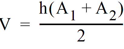
Determine wetpool dimensions. Determine the wetpool dimensions satisfying the design criteria outlined below and illustrated in Figure 4 - 36: Wetpond (top view) and Figure 4 - 37: Wetpond (side view). A simple way to check the volume of each wetpool cell is to use the following equation:
h = wetpool average depth (ft)
A1 = water quality design surface area of wetpool (sf)
A2 = bottom area of wetpool (sf)
Design pond outlet pipe and determine primary overflow water surface. The pond outlet pipe shall be placed on a reverse grade from the pond's wetpool to the outlet structure. Provide documentation on how the outlet pipe was sized. Volume 5 contains guidance for conveyance system design. Pipe sizing shall be based on backwater effects.
The primary design factor that determines a wetpond's efficiency is the wetpool volume. The larger the wetpool volume, the greater the potential for pollutant removal.
Also important are the avoidance of short-circuiting and promotion of plug flow. To prevent short-circuiting and promote plug flow, the pond should be designed to force water to flow to all potentially available routes avoiding dead zones and maximizing the time water stays in the pond during a storm event.
Design features that encourage plug flow and avoid dead zones are:
Dissipating energy at the inlet.
Providing a large length-to-width ratio.
Providing a broad surface for water exchange using a berm designed as a broad-crested weir to divide the wetpond into two cells rather than a constricted area such as a pipe.
Maximizing the flowpath between inlet and outlet, including the vertical path, enhances treatment by increasing residence time.
A small amount of base flow is desirable to maintain circulation and reduce the potential for low oxygen conditions during late summer.
15.1.3.3 Wetpool Geometry
Divide the wetpool into two cells separated by a baffle or berm. The first cell shall contain between 25 to 35 percent of the total wetpool volume. The baffle or berm volume shall not count as part of the total wetpool volume.
Provide sediment storage in the first cell. The sediment storage shall have a minimum depth of 1-foot. Install a fixed sediment depth monitor in the first cell to gauge sediment accumulation unless an alternative gauging method is proposed.
The minimum depth of the first cell shall be 4 feet, exclusive of sediment storage requirements. The depth of the first cell may be greater than the depth of the second cell.
The maximum depth of each cell shall not exceed 8 feet (exclusive of sediment storage in the first cell). Plant pool depths of 3 feet or shallower (second cell) with emergent wetland vegetation (see planting requirements).
Place inlets and outlets to maximize the flowpath through the facility. The ratio of flowpath length to width from the inlet to the outlet shall be at least 3:1. The flowpath length is defined as the distance from the inlet to the outlet, as measured at mid-depth. The width at mid-depth can be found as follows: width = (average top width + average bottom width)/2.
Wetponds with wetpool volumes less than or equal to 4,000 cubic feet may be single celled (i.e., no baffle or berm is required). However, it is especially important in this case that the flowpath length be maximized. The ratio of flowpath length to width shall be at least 4:1 in single celled wetponds, but should preferably be 5:1.
All inlets shall enter the first cell. For multiple inlets, the length-to-width ratio shall be based on the average flowpath length for all inlets.
Line the first cell in accordance with the liner requirements contained in A100 - Liners.
For wetpool depths in excess of 6 feet, it is recommended that some form of recirculation be provided in the summer, such as a fountain or aerator, to prevent stagnation and low dissolved oxygen conditions.
A tear-drop shape, with the inlet at the narrow end, rather than a rectangular pond is preferred since it minimizes dead zones caused by corners.
15.1.3.4 Berms, Baffles, and Slopes
A berm or baffle shall extend across the full width of the wetpool, and tie into the wetpond side slopes. If the berm embankments are greater than 4 feet in height, the berm must be constructed by excavating a key with dimensions equal to 50 percent of the embankment cross-sectional height and width. This requirement may be waived if recommended by a Washington State Licensed Professional Engineer or Washington State Licensed Professional Geologist for specific site conditions. The geotechnical analysis shall address situations in which one of the two cells is empty while the other remains full of water.
The top of the berm may extend to the WQ design water surface or be 1-foot below the WQ design water surface. If at the WQ design water surface, berm side slopes shall be 3H:1V. Berm side slopes may be steeper (up to 2H:1V) if the berm is submerged 1-foot.
If good vegetation cover is not established on the berm, erosion control measures shall be used to prevent erosion of the berm back-slope when the pond is initially filled.
The interior berm or baffle may be a retaining wall provided that the design is prepared and stamped by a Washington State Licensed Professional Engineer. If a baffle or retaining wall is used, it shall be submerged one foot below the design water surface to discourage access by pedestrians.
Side slopes shall not exceed a slope of 3H:1V. Moderately undulating slopes are acceptable and can provide a more natural setting for the facility. In general, gentle side slopes improve the aesthetic attributes of the facility and enhance safety.
Interior side slopes may be retaining walls. Retaining walls require design and stamp by a Washington State Licensed Professional Engineer.
See Figure 4 - 37: Wetpond (side view) for details on the following requirements:
Submerge the inlet to the wetpond with the inlet pipe invert a minimum of two feet from the pond bottom (not including sediment storage). The top of the inlet pipe shall be submerged at least 1-foot, if possible.
Provide an outlet structure. Either a Type 2 catch basin with a grated opening or a maintenance hole with a beehive grate may be used (see Figure 4 - 73: Overflow Structure for an illustration). A sump is not required in the outlet structure for wetponds that do not provide detention storage.
The pond outlet pipe (as opposed to the maintenance hole or type 2 catch basin outlet pipe) shall be back-sloped or have a down-turned elbow, and extend 1 foot below the WQ design water surface.
Size the pond outlet pipe, at a minimum, to pass the online WQ design flow. The highest invert of the outlet pipe sets the WQ design water surface elevation.
The overflow criteria for single-purpose (treatment only, not combined with flow control) wetponds are as follows:
The requirement for primary overflow is satisfied by either the grated inlet to the outlet structure or by a beehive grate above the pond outlet structure.
The bottom of the grate opening in the outlet structure shall be set at or above the height needed to pass the WQ design flow through the pond outlet pipe. The grate invert elevation sets the overflow water surface elevation.
The grated opening and downstream conveyance shall be sized to pass the 100-year design flow. The capacity of the outlet system shall be sized to pass the peak volumetric flowrate for the conveyance requirements.
In addition to the primary overflow, ponds must have an emergency overflow spillway. Design the Emergency Overflow Spillway per A600 - Emergency Overflow Spillway.
The City may require a bypass/shutoff valve to enable the pond to be taken offline for maintenance purposes.
A gravity drain for maintenance is recommended if grade allows.
The drain invert shall be at least 6 inches below the top elevation of the dividing berm or baffle. Deeper drains are encouraged where feasible, but must be no deeper than 18 inches above the pond bottom.
The drain shall be at least 8 inches (minimum) diameter and shall be controlled by a valve. Use of a shear gate is allowed only at the inlet end of a pipe located within an approved structure.
Provide operational access to the valve at the finished ground surface.
The valve location shall be accessible and well marked with 1-foot of paving placed around the box. It must also be protected from damage and unauthorized operation.
A valve box is allowed to a maximum depth of 5 feet without an access maintenance hole. If over 5 feet deep, an access maintenance hole or vault is required.
Acceptable materials for other parts of the wetpond include thermoplastics, iron, steel, aluminum, and concrete. Steel and iron shall be aluminum coated (aluminized Type 2). Zinc coated (galvanized) materials are prohibited. Painted metal parts shall not be used because of poor longevity.
The number of inlets to the facility should be limited; ideally there should be only one inlet. The flowpath length should be maximized from inlet to outlet for all inlets to the facility.
All facilities shall be a minimum of 20 feet from any structure or property line.
Provide maintenance access road(s) to the inlet and outlet. Access roads and ramps shall conform to A3000 - Access Ramps and Roads.
An access ramp is required for removal of sediment. For small, shallow ponds, an access ramp may not be required if the trackhoe can load a truck parked at the pond edge. Extend the access ramp to the bottom of the first cell unless all portions of the cell can be reached and sediment loaded from the top of the pond.
The internal berm may be used as access only if all the following apply:
The internal berm is no more than 4' above the first wetpool cell.
The first wetpool cell is less than 1,500 square feet (measured without the ramp)
The internal berm is designed to support a loaded truck, 80,000 pounds minimum, considering the berm is normally submerged and saturated.
15.1.3.7 Planting Requirements
Planting requirements for Wetponds are the same as Detention Ponds with additional considerations for planting as noted below. See BMP F100 - Detention Facilities.
Large wetponds intended for phosphorus control shall not be planted within the cells, as the plants will release phosphorus in the winter when they die off. The bottom and side slopes shall be stabilized to prevent erosion.
If the second cell of a basic wetpond is 3 feet deep or shallower, the bottom area shall be planted with emergent wetland vegetation. See A1000 - Vegetation for recommended emergent wetland plant species for wetponds. The recommendations in A1000 - Vegetation for recommended plant species for wetponds are for all of western Washington. Local knowledge should be used to tailor this information to Tacoma as appropriate.
Cattails (Typha latifolia) shall not be used because they tend to crowd out other species.
If the wetpond discharges to a phosphorus-sensitive lake or wetland, shrubs that form a dense cover should be planted on slopes above the WQ design water surface on at least three sides. Native vegetation species shall be used in all cases. No planting on berms or banks is allowed if the wetpond is regulated as a dam.
Provide a planting plan that shows mature plant coverage and species type.
Evergreen or columnar deciduous trees along the west and south sides of ponds are recommended to reduce thermal heating, except that no trees or shrubs may be planted on berms meeting the criteria of dams regulated for safety. In addition to shade, trees and shrubs also discourage waterfowl use and the phosphorus enrichment problems they cause. Trees should be set back so that the branches will not extend over the pond.
Landscaping considerations are the same as BMP F110 - Detention Ponds.
Provide a stormwater facility sign. Sign shall conform to A800 - Signage.
The following design features should be incorporated to enhance aesthetics where possible:
Provide pedestrian access to shallow pool areas enhanced with emergent wetland vegetation. This allows the pond to be more accessible without incurring safety risks.
Provide side slopes that are sufficiently gentle to avoid the need for fencing (3H:1V or flatter).
Create flat areas overlooking or adjoining the pond for picnic tables or seating that can be used by residents. Walking or jogging trails around the pond are easily integrated into site design.
Include fountains or integrated waterfall features for privately maintained facilities.
Provide visual enhancement with clusters of trees and shrubs. On most pond sites, it is important to amend the soil before planting since ponds are typically placed well below the native soil horizon in very poor soils. Make sure dam safety restrictions against planting do not apply.
Orient the pond length along the direction of prevailing summer winds (typically west or southwest) to enhance wind mixing.
Remove sediment that has accumulated in the pond after construction is complete (unless used for a liner - see below).
Sediment that has accumulated in the pond at the end of construction may be used as a liner in high permeability soils if the sediment meets the criteria for low permeability or treatment liners in keeping with guidance given in Chapter 1. Sediment used for a soil liner must be graded to provide uniform coverage and must meet the thickness specifications in Chapter 1. The sediment must not reduce the design volume of the pond. The pond must be over-excavated initially to provide sufficient room for the sediments to serve as a liner.


