15.3 BMP T1130 - Stormwater Treatment Wetlands
Stormwater treatment wetlands are shallow artificial ponds that are designed to treat stormwater through the biological processes associated with emergent aquatic plants (see the stormwater wetland details in Figure 4 - 39: Stormwater Wetland – Option 1 and Figure 4 - 40: Stormwater Wetland – Option 2).
Wetlands created to mitigate disturbance impacts, such as filling of wetlands, shall not be used as stormwater treatment facilities.
15.3.2 Applications and Limitations
Stormwater treatment wetlands can be used to ensure compliance with Minimum Requirement 6 - Stormwater Treatment.
Stormwater treatment wetlands can be used alone to meet Enhanced Treatment and Basic Treatment. When used as part of a treatment train with either a Basic Sand Filter Basin or Sand Filter Vault, stormwater treatment wetlands can provide Phosphorus Treatment.
The most critical factor for a successful design is the provision of an adequate supply of water for most of the year. Since water depths are shallower than in wetponds, water loss by evaporation is an important concern. Stormwater wetlands are a good facility choose for ensuring compliance with Minimum Requirement 6 - Stormwater Treatment in areas with high winter groundwater levels.
Stormwater wetlands use most of the same design criteria as wetponds. However, instead of gravity settling being the dominant treatment process, pollutant removal mediated by aquatic vegetation and the microbiological community associated with that vegetation becomes the dominant treatment process. Thus when designing wetlands, water volume is not the dominant design criteria. Rather, factors which affect plant vigor and biomass are the primary concerns.
Comply with all criteria and standards in Modeling Your Best Management Practices, Design Criteria for All Stormwater Treatment and Flow Control BMPs, Constructing Your Best Management Practices and Accessing and Maintaining Your Best Management Practices as applicable to the project in addition to criteria within each BMP. Where criteria or standards conflict, utilize the criteria and standards contained within the specific BMP.
Stormwater treatment wetlands may be located upstream or downstream of detention facilities. Stormwater treatment wetlands located downstream from detention may have better plant diversity.
Calculate the design volume (V). The stormwater treatment wetland design volume shall be equal to or greater than the water quality design storm volume. The wetpool volume shall be calculated using an Ecology approved continuous simulation model, assuming a 15-minute timestep, to obtain the water quality design volume.
Calculate the surface area (A) of the stormwater wetland using the equation below:
Atotal - Surface Area of the Stormwater Wetland (ft2)
Davg - Average Water Depth (ft) = 3
Determine the surface area of the presettling cell (first cell) of the stormwater treatment wetland using the equations below.
Vpre = Volume of the Presettling Cell (ft3)
Vtotal=Design Volume (ft3) as calculated in Step 1.
Apre - Surface Area of the Presettling Cell (ft2)
Vpre - Volume of the Presettling Cell (ft3)
Dpre - Depth of Presettling cell (ft) = between 4 and 8 feet.
Determine the surface area of the wetland cell (second cell).

Determine water depth distribution in the second cell. Decide if the top of the dividing berm will be at the surface or submerged (designer's choice). Adjust the distribution of water depths in the second cell according to Step 8 in below in Section 15.3.3.2 Wetland Geometry. This will result in a facility that holds less volume than that determined in Step 1 above. This is acceptable.
Choose plants. See A1000 - Vegetation for a list of plants recommended for wetpond water depth zones, or consult a wetland scientist.
15.3.3.2 Wetland Geometry
Stormwater wetlands shall consist of two cells, a presettling cell and a wetland cell.
The presettling cell shall contain approximately 33 percent of the total wetland volume.
The depth of the presettling cell shall be between 4 feet (minimum) and 8 feet (maximum), excluding sediment storage.
Provide one-foot of sediment storage in the presettling cell.
The wetland cell shall have an average water depth of about 1.5 feet (plus or minus 3 inches).
Shape the "berm" separating the two cells such that its downstream side gradually slopes to form the second shallow wetland cell (see the section view in Figure 4 - 39: Stormwater Wetland – Option 1). Alternatively, the second cell may be graded naturalistically from the top of the dividing berm (see 8 below).
The top of the berm shall be either at the WQ design water surface or submerged 1-foot below the WQ design water surface. Correspondingly, the side slopes of the berm must meet the following criteria:
a If the top of berm is at the WQ design water surface, the berm side slopes shall be no steeper than 3H:1V.
b If the top of berm is submerged 1-foot, the upstream side slope may be up to 2H:1V.
Grade the bottom of the wetland cell in one of two ways:
a Shallow evenly graded slope from the upstream to the downstream edge of the wetland cell (see Figure 4 - 39: Stormwater Wetland – Option 1).
b A "naturalistic" alternative, with the specified range of depths intermixed throughout the second cell (see Figure 4 - 40: Stormwater Wetland – Option 2). A distribution of depths shall be provided in the wetland cell depending on whether the dividing berm is at the water surface or submerged.
The maximum depth shall be 2.5 feet in either configuration.
15.3.3.3 Lining Requirements
Stormwater treatment wetlands are not intended to infiltrate. In infiltrative soils, line both cells of the stormwater wetland. To determine whether a low-permeability liner or a treatment liner is required, determine whether the following conditions will be met. If soil permeability will allow sufficient water retention, lining may be waived.
The second cell must retain water for at least 10 months of the year.
The first cell must retain at least three feet of water year-round.
Use a complete precipitation record when establishing these conditions. Take into account evapotranspiration losses as well as infiltration losses. Many wetland plants can adapt to periods of summer drought, so a limited drought period is allowed in the second cell. This may allow a treatment liner rather than a low permeability liner to be used for the second cell. The first cell must retain water year-round in order for the presettling function to be effective.
If a low permeability liner is used, place a minimum of 18 inches of native soil amended with good topsoil or compost (one part compost mixed with 3 parts native soil) over the liner. For geomembrane liners, a soil depth of 3 feet is recommended to prevent damage to the liner during planting. Hydric soils are not required.
See A100 - Liners for additional information.
See Figure 4 - 39: Stormwater Wetland – Option 1 and Figure 4 - 40: Stormwater Wetland – Option 2 for details on the following requirements:
Submerge the inlet to the stormwater treatment wetland with the inlet pipe invert a minimum of two feet from the stormwater treatment wetland bottom (not including sediment storage). The top of the inlet pipe shall be submerged at least 1-foot, if possible.
Provide an outlet structure. Either a Type 2 catch basin with a grated opening or a maintenance hole with a beehive grate may be used (see Figure 4 - 73: Overflow Structure for an illustration). A sump is not required in the outlet structure.
The stormwater treatment wetland outlet pipe (as opposed to the maintenance hole or type 2 catch basin outlet pipe) shall be back-sloped or have a down-turned elbow, and extend 1 foot below the WQ design water surface.
Size the stormwater treatment wetland outlet pipe, at a minimum, to pass the online WQ design flow. The highest invert of the outlet pipe sets the WQ design water surface elevation.
The overflow criteria for single-purpose (treatment only, not combined with flow control) stormwater treatment wetlands are as follows:
The requirement for primary overflow is satisfied by either the grated inlet to the outlet structure or by a beehive grate above the stormwater treatment wetland outlet structure.
The bottom of the grate opening in the outlet structure shall be set at or above the height needed to pass the WQ design flow through the stormwater treatment wetland outlet pipe. The grate invert elevation sets the overflow water surface elevation.
The grated opening and downstream conveyance shall be sized to pass the 100-year design flow. The capacity of the outlet system shall be sized to pass the peak flow for the conveyance requirements.
In addition to the primary overflow, stormwater treatment wetlands must have an emergency overflow spillway. Design the Emergency Overflow Spillway per A600 - Emergency Overflow Spillway.
The City may require a bypass/shutoff valve to enable the pond to be taken offline for maintenance purposes.
A gravity drain for maintenance is recommended if grade allows.
The drain invert shall be at least 6 inches below the top elevation of the dividing berm or baffle. Deeper drains are encouraged where feasible, but must be no deeper than 18 inches above the pond bottom.
The drain shall be at least 8 inches (minimum) diameter and shall be controlled by a valve. Use of a shear gate is allowed only at the inlet end of a pipe located within an approved structure.
Provide operational access to the valve to the finished ground surface.
The valve location shall be accessible and well marked with 1-foot of paving placed around the box. It must also be protected from damage and unauthorized operation.
A valve box is allowed to a maximum depth of 5 feet without an access maintenance hole. If over 5 feet deep, an access maintenance hole or vault is required.
Acceptable materials for other parts of the wetpond include thermoplastics, iron, steel, aluminum, and concrete. Steel and iron shall be aluminum coated (aluminized Type 2). Zinc coated (galvanized) materials are prohibited. Painted metal parts shall not be used because of poor longevity.
The number of inlets to the facility should be limited; ideally there should be only one inlet. The flowpath length should be maximized from inlet to outlet for all inlets to the facility.
All facilities shall be a minimum of 20 feet from any structure or property line.
Provide maintenance access road(s) to the inlet and outlet. Access roads and ramps shall conform to A3000 - Access Ramps and Roads.
Place maintenance hole lids in or at the edge of the access road when possible.
An access ramp is required for removal of sediment. For small, shallow ponds, an access ramp may not be required if the trackhoe can load a truck parked at the pond edge. Extend the access ramp to the bottom of the first cell unless all portions of the cell can be reached and sediment loaded from the top of the pond.
The internal berm may be used as access only if all the following apply:
The internal berm is no more than 4' above the first wetpool cell.
The first wetpool cell is less than 1,500 square feet (measured without the ramp)
The internal berm is designed to support a loaded truck, 80,000 pounds minimum, considering the berm is normally submerged and saturated.
15.3.3.6 Planting Requirements
Plant the wetland cell with emergent wetland plants following the recommendations given in A1000 - Vegetation for stormwater treatment wetlands or the recommendations of a wetland specialist. Cattails (Typha latifolia) are not allowed. Provide a planting plan showing mature plant coverage and species type.
Provide a stormwater facility sign. Sign shall conform to A800 - Signage.
15.3.3.8 Construction Criteria
Remove sediment that has accumulated in the pond after construction is complete (unless used for a liner - see below).
Sediment that has accumulated in the pond at the end of construction may be used as a liner in high permeability soils if the sediment meets the criteria for low permeability or treatment liners in keeping with guidance given in A100 - Liners. Sediment used for a soil liner must be graded to provide uniform coverage and must meet the thickness specifications in A100 - Liners. The sediment must not reduce the design volume of the pond. The pond must be over-excavated initially to provide sufficient room for the sediments to serve as a liner.
Construction of the naturalistic alternative (Option 2) can be accomplished by first excavating the entire area to the 1.5-foot average depth. Then soil subsequently excavated to form deeper areas can be deposited to raise other areas until the distribution of depths indicated in the design is achieved.
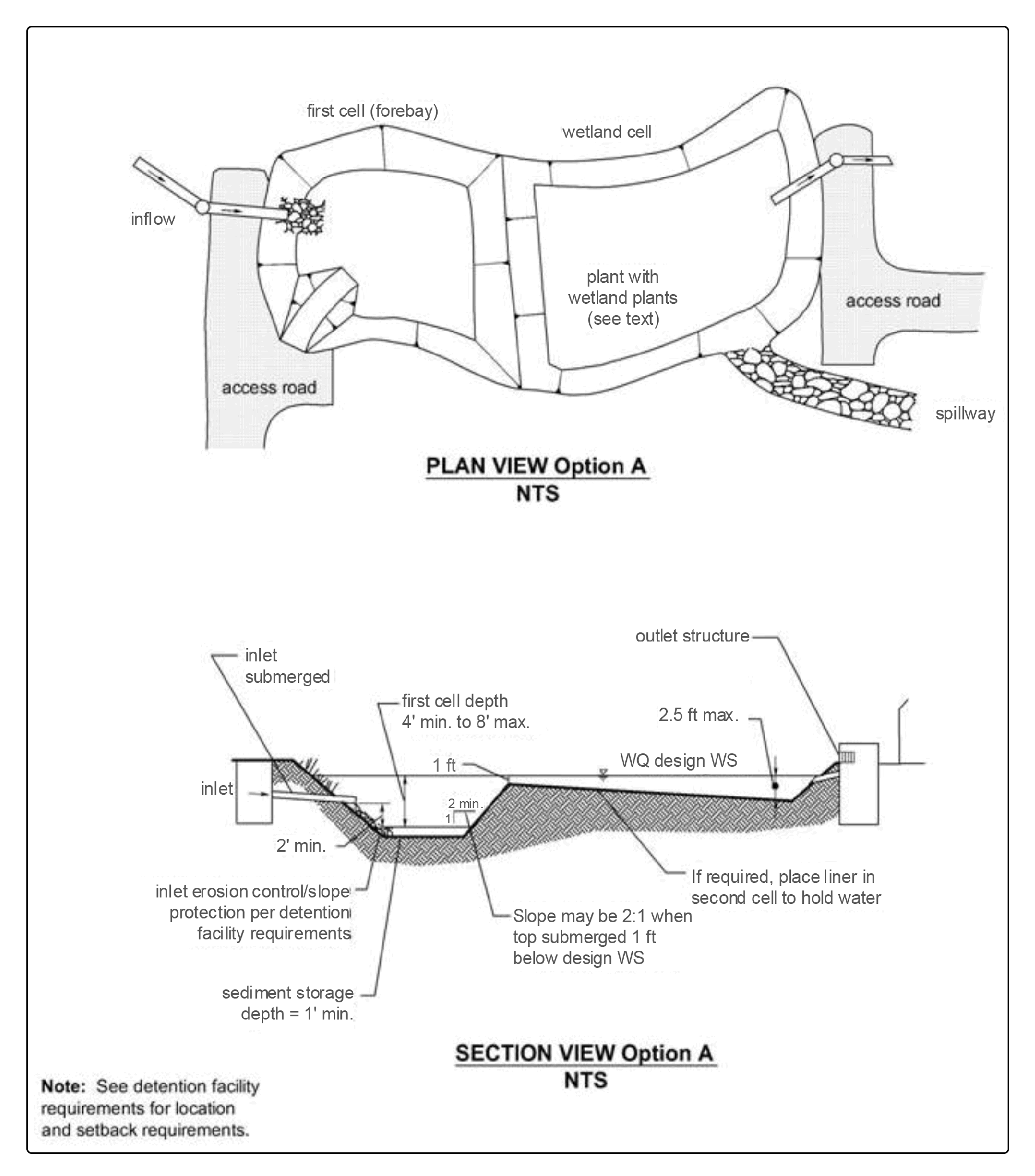
Figure 4 - 39: Stormwater Wetland – Option 1
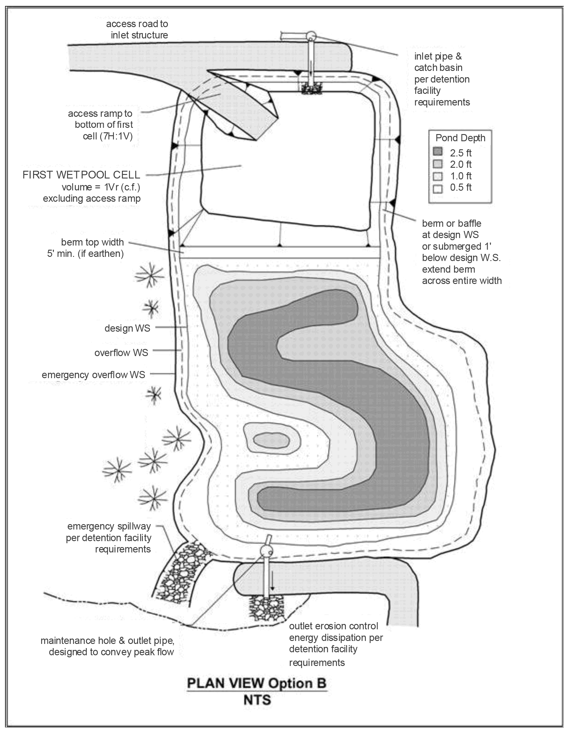
Figure 4 - 40: Stormwater Wetland – Option 2